
Roller structure of computer controlled flat knitting machine

A flat knitting machine roller and computer technology, applied in weft knitting, knitting, textile and papermaking, etc., can solve the problems of insufficient pulling effect and poor applicability, and achieve the effect of taking into account the compactness and the increased pressure of the compression spring

Inactive Publication Date: 2014-05-07
SHAOXING JINHAO MACHINERY MFG
View PDF9 Cites 0 Cited by
  • Summary
  • Abstract
  • Description
  • Claims
  • Application Information

AI Technical Summary

Problems solved by technology

[0004] In order to overcome the shortcomings of insufficient pulling effect and poor applicability of the existing computerized flat knitting machine roller structure, the present invention provides a kind of fabric that has good pulling effect and strong applicability and can positively increase the roller pre-tightening pressure. Roller structure to reduce roller pressure

Method used


Image

  • Roller structure of computer controlled flat knitting machine
  • Roller structure of computer controlled flat knitting machine
  • Roller structure of computer controlled flat knitting machine

Examples


Embodiment Construction

[0028] The present invention will be further described below by specific embodiment:

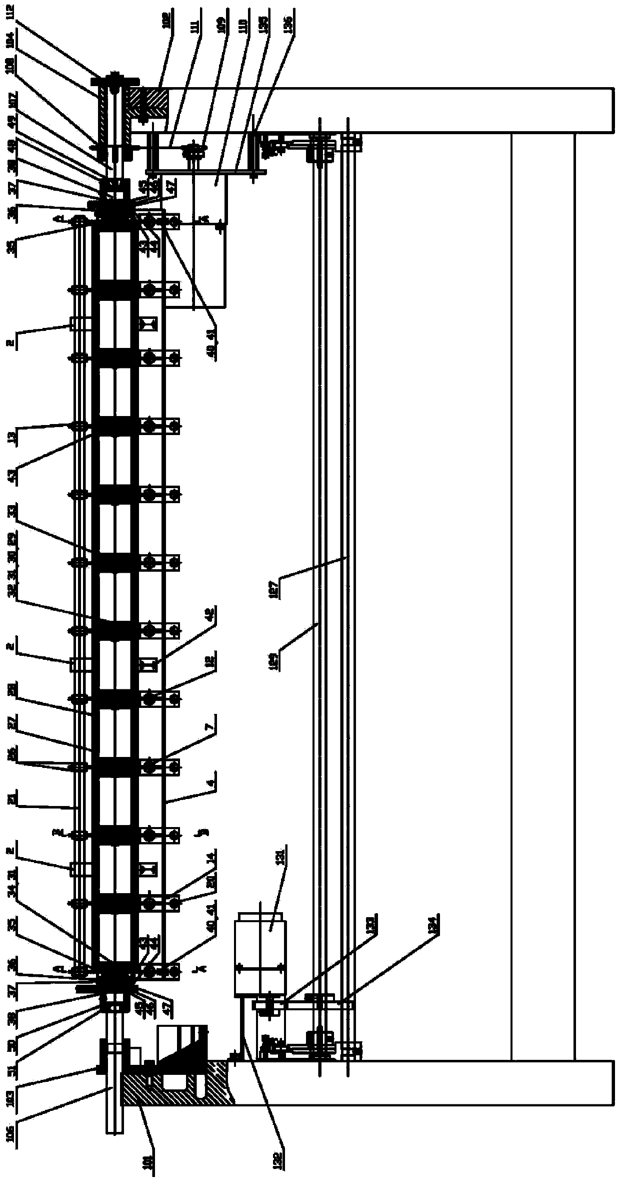
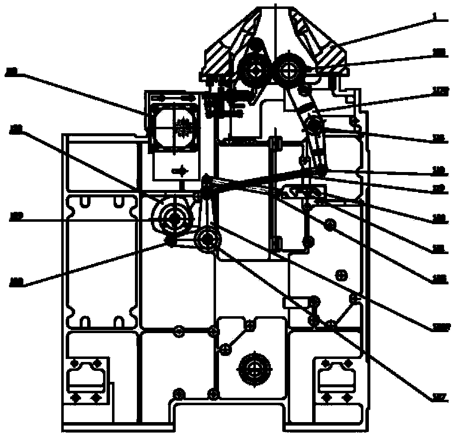
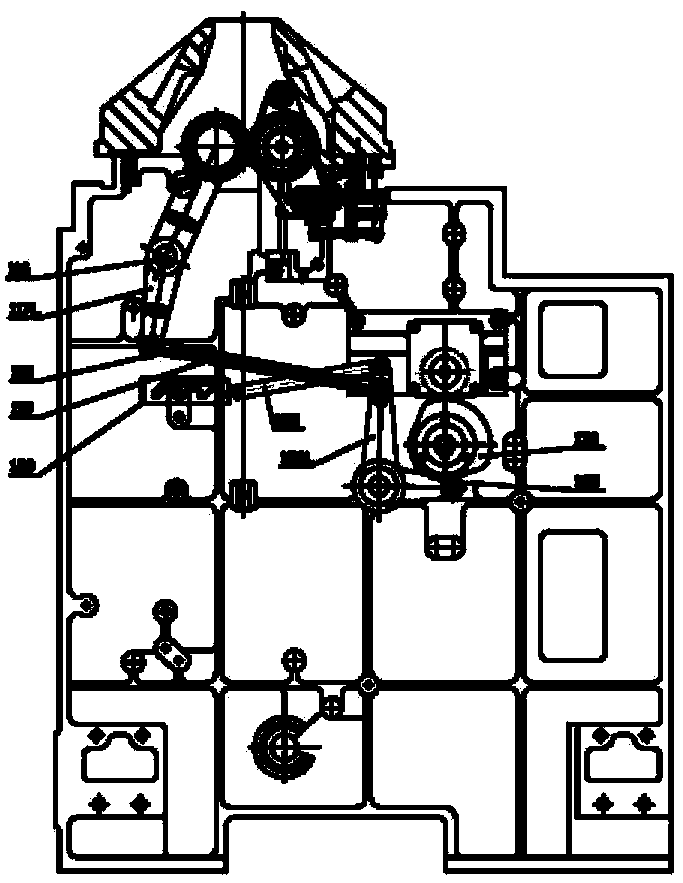
[0029] refer to figure 1 — Figure 7 , a computer knitting flat knitting machine roller structure, including a front roller 105F, a rear roller 105B, a support mechanism for fixing the front roller and the rear roller, a first torque motor 110 driving the rotation of the front roller and the rear roller, and controlling the closing of the front roller and the rear roller The second torque motor 131.

[0030] Roller transmission structure see figure 1 - Figure 4 , the left bracket 103 is installed on the left wallboard 101 of the frame, and the right bracket 104 is installed on the right wallboard 102 of the frame, figure 1 , 4 The rear roller 105B of the rear roller 105B is respectively installed on the supporting mechanism on the left wallboard 101 and the right wallboard 102 with the shaft 106 and the drive shaft 107, and the inner deep groove rolling bearing 43 center of the roller ...


PUM


Abstract

The invention relates to a roller structure of a computer controlled flat knitting machine, which comprises a front roller, a back roller, a bracket, a first torque motor for driving the front roller and the back roller to rotate, and a second torque motor for controlling the front roller and the back roller to close, wherein the back roller comprises a plurality of roller units and connecting pieces among adjacent roller units, and the back roller is also provided with roller pretension pressure regulating devices. In the invention, the originally fixed integral main roller is axially divided into a plurality of roller units which are connected by the connecting pieces, and the roller pretension pressure regulating devices are arranged among the units, so that the structure is compact, can regulate the magnitude of the knitting tension in each regional section, and has good draw-off regulating effect on fabric and strong applicability.

Description

technical field [0001] The invention belongs to the technical field of textile equipment, and specifically relates to a computerized flat knitting machine roller structure with a lifting plate, in particular to a computerized flat knitting machine main roller structure with a traction tension adjustment mechanism. The top roller realizes the positive increase of the pre-tightening force and the reverse decompression force to adjust the stretching tension of the fabric in different transverse regions. Background technique [0002] The computerized flat knitting machine with a lifting plate needs to set the front and rear rollers to pull the knitted fabric, because one of the front and rear rollers needs to be fixed, and the other roller is dynamically adjusted; during the fabric pulling process, the front and rear rollers are closed and driven, The front and rear roller top rollers need to have a certain pressing force, and the size of the pressing force depends on the woven ...

Claims


Application Information

Patent Timeline
Patent Type & Authority Patents(China)
IPC IPC(8): D04B15/90
Inventor 陈永生孟鑫焱
Owner SHAOXING JINHAO MACHINERY MFG
Learn More