Electromagnetic synchronizer actuating system

A synchronizer, actuation technology, applied in the direction of transmission control, elements with teeth, belts/chains/gears, etc.

Inactive Publication Date: 2011-05-11
GM GLOBAL TECH OPERATIONS LLC
View PDF7 Cites 28 Cited by
  • Summary
  • Abstract
  • Description
  • Claims
  • Application Information

AI Technical Summary

Problems solved by technology

The first control coil is located near the permanent magnet
The second control coil is located near the permanent magnet

Method used


Image

  • Electromagnetic synchronizer actuating system
  • Electromagnetic synchronizer actuating system
  • Electromagnetic synchronizer actuating system

Examples


Embodiment Construction

[0053] The following description is merely exemplary in nature and is not intended to limit the invention, application or uses.

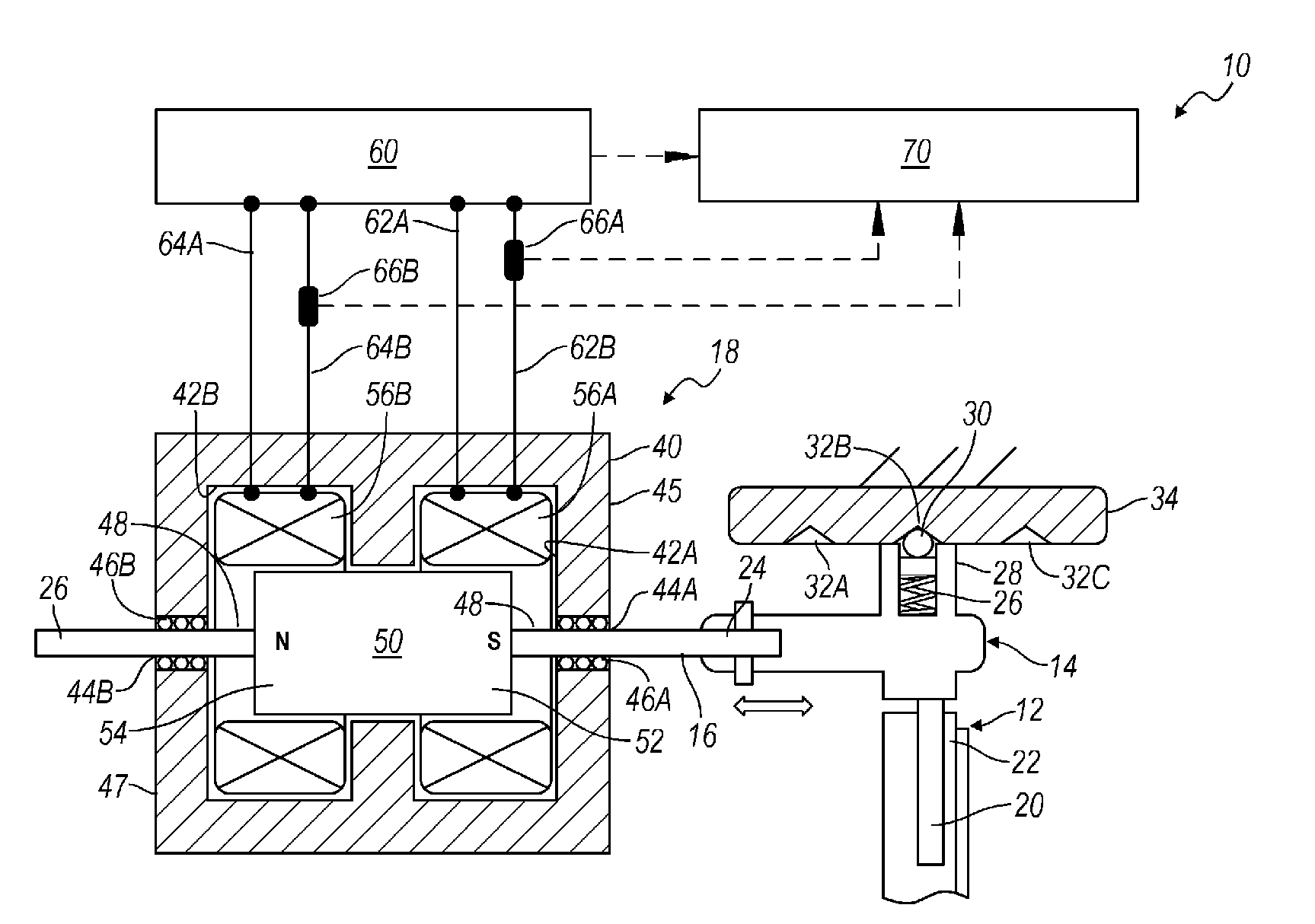
[0054] refer to figure 1 , reference numeral 10 shows and generally indicates a synchronizer actuation assembly. The synchronizer actuation assembly 10 is configured to actuate at least one synchronizer 12 in an automated manual transmission or a dual clutch transmission. The transmission may have any number of synchronizers 12 and any number of synchronizer actuation assemblies 10 without departing from the scope of the present invention. Synchronizer 12 is a bi-directional synchronizer movable between a first engaged position, a second engaged position, and a neutral or disengaged position. In each engaged position, synchronizer 12 is operable to rotationally couple two components, such as shafts and gears, together to transmit torque therebetween. In a neutral position, synchronizer 12 is not engaged with at least one of the components and is ...


PUM


Abstract

An assembly for actuating a synchronizer includes a shift fork, a shift rail, and a permanent magnet connected to the shift rail. A first control coil is disposed in proximity to the permanent magnet. The first control coil is operable to produce a magnetomotive force on the permanent magnet in a first direction when a current is applied to the first control coil. A second control coil is disposed in proximity to the permanent magnet. The second control coil is operable to produce a magnetomotive force on the permanent magnet in a second direction when a current is applied to the second control coil. The permanent magnet is moved to a first position when the current is applied to the first control coil and the permanent magnet is moved to a second position when the current is applied to the second control coil. Movement of the magnet in turn moves the synchronizer between engaged positions.

Description

technical field [0001] The present invention relates to electromagnetic actuation systems in transmissions, and more particularly, to a three-position electromagnetic synchronizer actuation system with self-positioning sensing capability. Background technique [0002] The statements in this section merely provide background information related to the present disclosure and may or may not constitute prior art. [0003] A typical manual transmission or dual clutch transmission (DCT) includes multiple gear sets selectively engaged by multiple torque-transmitting devices such as dog clutches or synchronizers. Preferably, the synchronizer moves between one or both of an engaged position and a neutral position. The synchronizers are actuated by synchronizer actuators. A synchronizer actuator generally includes a shift fork connected to the synchronizer, a shift rail connected to the shift fork, and an actuator that contacts and moves the shift rail. Typically, these actuators t...

Claims


Application Information

Patent Timeline
Patent Type & Authority Applications(China)
IPC IPC(8): F16H59/04F16H63/30
CPCF16H61/28F16H2061/2853F16H2063/305Y10T74/19251Y10T74/20183Y10T74/20177Y10T74/2003
Inventor S.白V.A.尼拉肯坦P.G.奥塔内斯
Owner GM GLOBAL TECH OPERATIONS LLC
Why Eureka
Try Eureka