Perpendicular thin-film magnetic head

a thin-film magnetic head and perpendicular technology, applied in the direction of heads with metal sheet cores, instruments, record information storage, etc., can solve the problems of difficult to provide a narrow track width of 1 .mu.m or below, heavy load on the driver circuit to supply recording current,

Inactive Publication Date: 2001-02-27
KK TOSHIBA
View PDF8 Cites 15 Cited by
  • Summary
  • Abstract
  • Description
  • Claims
  • Application Information

AI Technical Summary

Problems solved by technology

Since the conventional single-turn head or few-turns head requires a recording current larger by a factor of several tens than that of the writing/reading head, the burden on the driver circuit to supply the recording current is very heavy.
What is more, because of the large current, the heat generated by the coil portion will deteriorate the characteristic and reliability of the head.
Further, since the thickne...

Method used


Image

  • Perpendicular thin-film magnetic head
  • Perpendicular thin-film magnetic head
  • Perpendicular thin-film magnetic head

Examples


embodiment 1

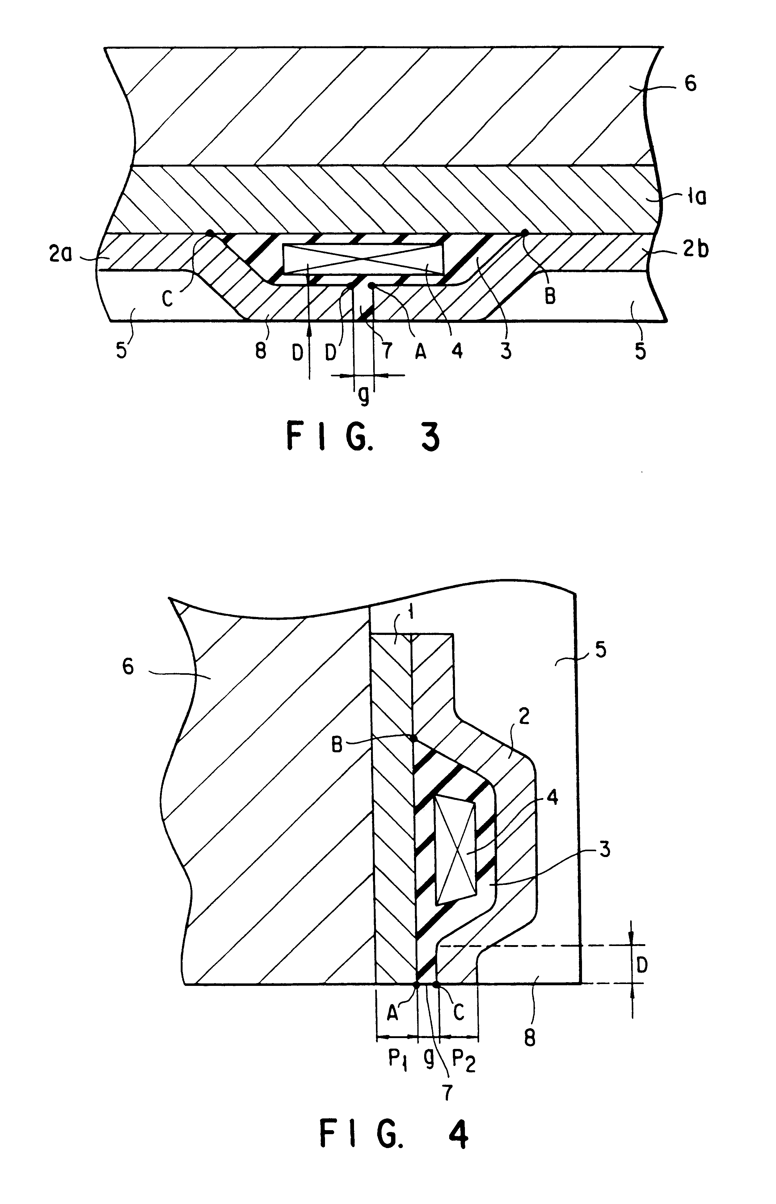
FIG. 3 is a cross section showing a thin-film magnetic head according to the first embodiment of this invention. This thin-film magnetic head is a ring-shaped horizontal (planar) type thin-film magnetic head, which comprises a magnetic layer 1a, an insulating layer 3, a coil 4, a magnetic layer 2a, a magnetic layer 2b and a head protective layer 5 laminated in order on a head substrate 6, with a magnetic gap 7 sandwiched between the magnetic layers 2a and 2b.

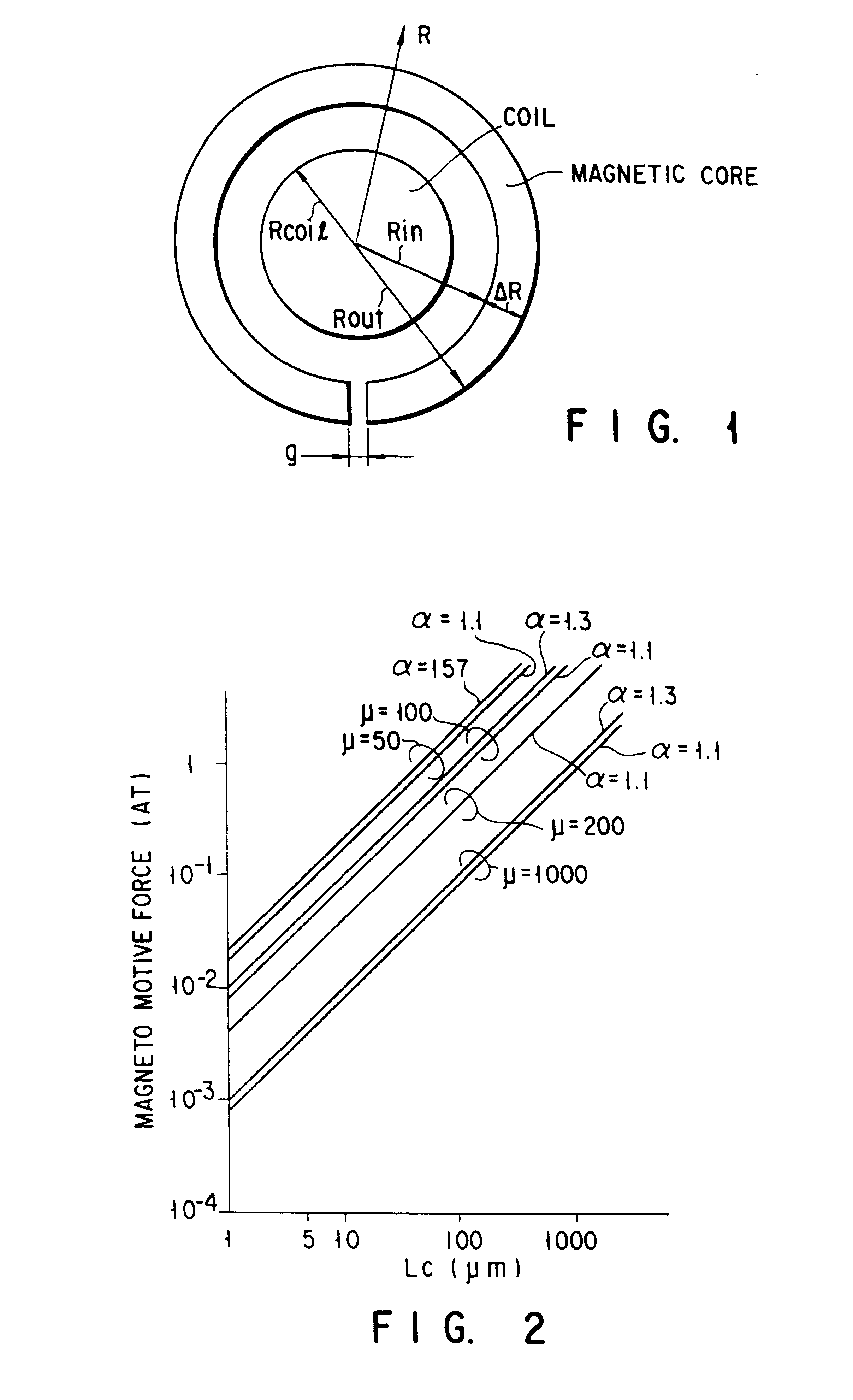
Let us put that a magnetic gap depth is D, a magnetic gap length is g, the inner circumferential length (length of the line A-B-C-D) of a magnetic core, which consists of the magnetic layers 1a, 2a and 2b and surrounds the coil 4 is Lc, an average magnetic flux density (unit: T (tesla)) necessary to generate a predetermined recording magnetic field needed to magnetize a magnetic recording medium is Bav, and the effective magnetic permeability of the ring-shaped magnetic core is .mu., as shown in FIG. 3.

As described above, the th...

embodiment 2

FIG. 4 is a cross section showing a thin-film magnetic head according to the second embodiment of this invention. This thin-film magnetic head is a ring-shaped thin-film magnetic head, which comprises a lower magnetic pole 1, an insulating layer 3, a coil 4, an upper magnetic pole 2 and a head protective layer 5 laminated in order on a head substrate 6, with a magnetic gap 7 sandwiched between the lower magnetic pole 1 and the upper magnetic pole 2.

Given that a magnetic gap length is g, a magnetic gap depth is D, the thickness of the lower magnetic pole 1 on the medium opposing face 8 is P1, the thickness of the upper magnetic pole 2 on the medium opposing face 8 is P2, the inner circumferential length (length of the line A-B-C) of the magnetic core, which consists of the lower magnetic pole 1 and the upper magnetic pole 2 and surrounds the coil 4 is Lc, an average magnetic flux density (unit: T (tesla)) necessary to generate a predetermined recording magnetic field needed to magnet...

embodiment 3

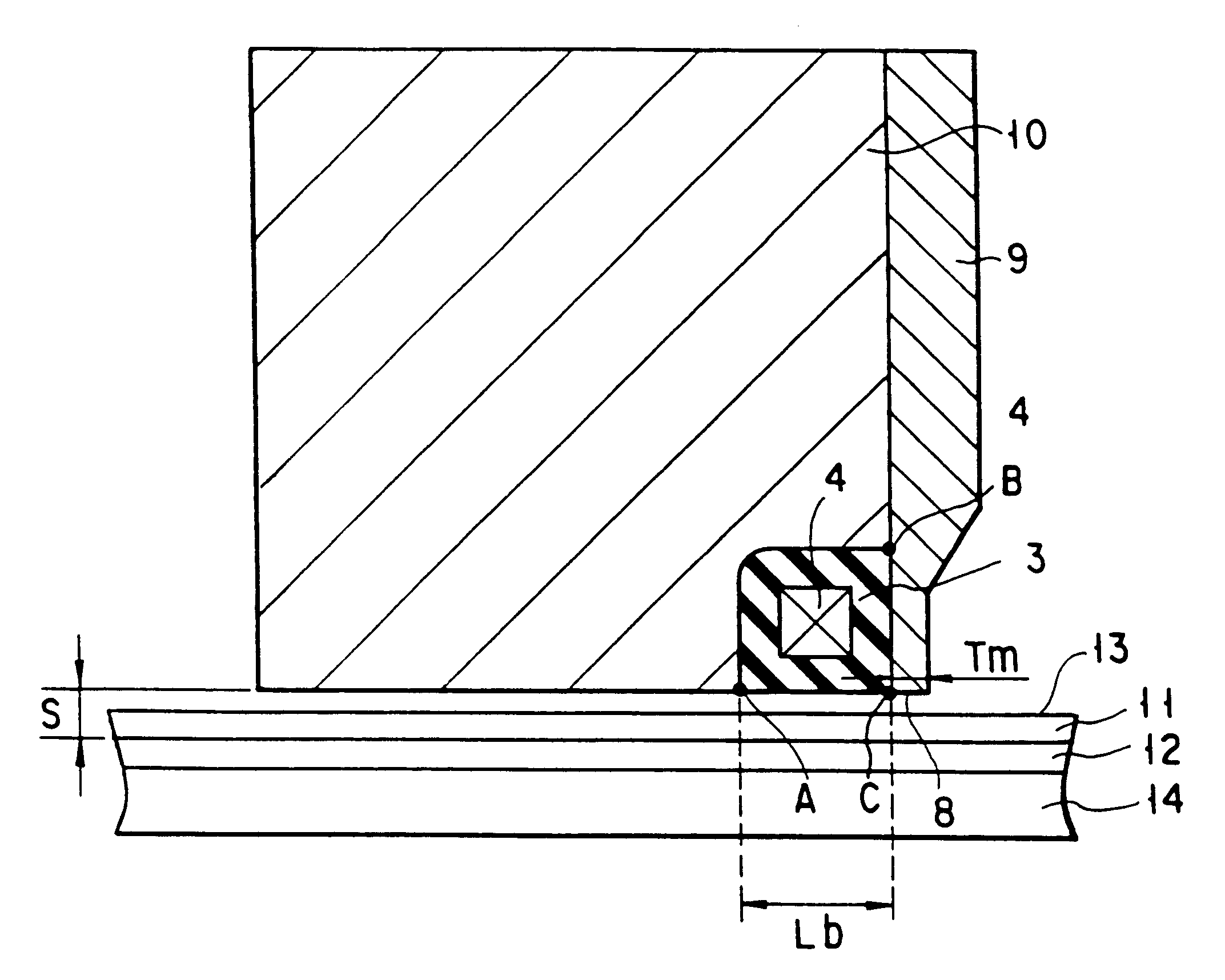
FIG. 5 is a cross section showing a perpendicular thin-film magnetic head according to the third embodiment of this invention. This perpendicular thin-film magnetic head performs recording and reproduction when in use with a perpendicular double-layered magnetic recording medium 13, which has a highly permeable layer 12 and a perpendicular recording layer 11 laminated in this order on a medium substrate 14.

This perpendicular thin-film magnetic head comprises a magnetic core having a main magnetic pole 9 and a highly permeable return path 10, which is magnetically coupled to this main magnetic pole 9, and a coil 4 which is surrounded by the magnetic core through an insulating layer 3.

Given that the inner circumferential length (length of the line A-B-C-D) of the magnetic core surrounding the coil 4 is Lc, the distance from the medium opposing face 8 of the perpendicular thin-film magnetic head to the recording-layer side face of the highly permeable layer 12 of the perpendicular doub...


PUM


Abstract

Disclosed is a thin-film magnetic head comprising a ring-shaped magnetic core and a coil surrounded by the magnetic core, given that an inner circumferential length of the magnetic core surrounding the coil is Lc, a magnetic gap length is g, a magnetic gap depth is D, an average magnetic flux density (unit: T (tesla)) is Bav and an effective magnetic permeability of the magnetic core is mu, Lc, g and D being determined in such a manner that a magnetomotive force I needed for recording, expressed by a following equation (1), becomes equal to or less than 0.1 A.T (Ampere.Turn):where Log is a natural logarithm, and variables in the equation (1) are expressed in SI units.

Description

1. Field of the InventionThe present invention relates to a thin-film magnetic head for use in a magnetic disk apparatus, a VTR, etc., and a magnetic write / read apparatus equipped with this magnetic head, and more particularly, to a very small thin-film magnetic head which has low recording magnetomotive force necessary for magnetizing a magnetic recording medium, has a fewer number of recording coil turns and has a very narrow track width, and a magnetic write / read apparatus equipped with this magnetic head.2. Description of the Related ArtFor an inductive magnetic head which has been conventionally popular, when used both for writing and reading, it is in principle advantageous to increase the number of coil turns because this provides a larger reading output. With such a magnetic head used exclusively for information writing, however, the number of coil turns can be reduced as long as the magnetomotive force required for writing is satisfied. The inductive magnetic head for exclu...

Claims


Application Information

Patent Timeline
IPC IPC(8): G11B5/49G11B5/012G11B5/00G11B5/127
CPCG11B5/1278G11B5/012G11B2005/0029
Inventor AKIYAMA, JUNICHIYODA, HIROAKI
Owner KK TOSHIBA
Why Eureka
Try Eureka