Multi-axis Magnetic Lens for Focusing a Plurality of Charged Particle Beams

a magnetic lens and charged particle technology, applied in the field of multi-axis magnetic lenses, can solve the problems of insufficient mass production of electron beams, insufficient number of electron beams available for wafers or masks, and fundamentally deterioration of superior spatial resolution, so as to achieve efficient reduction of non-axisymmetric transverse field components and high permeability

Active Publication Date: 2013-06-20
ASML NETHERLANDS BV
View PDF3 Cites 15 Cited by
  • Summary
  • Abstract
  • Description
  • Claims
  • Application Information

AI Technical Summary

Benefits of technology

[0020]The multi-axis magnetic immersion objective lens according to the present invention may further comprise an upper magnetic shielding plate located above the upper magnetic conductor plate and a lower magnetic shielding plate located between the lower magnetic conductor plate and the specimen, wherein the upper and lower magnetic shielding plates have a plurality of circular openings aligned with the plurality of through round holes respectively so as to efficiently reduce non-axisymmetric transverse field components above and below the upper and lower magnetic conductor plates respectively. The multi-axis magnetic immersion objective lens may still comprise a magnetic stage located below the specimen to sustain the specimen thereon, wherein the magnetic stage magnetically couples with the upper and lower pole-pieces of each sub-lens module to create a strong magnetic field immersion on the upper surface of the specimen.
[0021]All the magnetic sub-lens modules are configured to have same focusing power by using a specific arrangement of thickness differences and / or permeability differences among the plurality of upper radial gaps. For each magnetic sub-lens module, the magnetic ring and the specimen are electrically excited to act as an electrostatic sub-lens so that every magnetic sub-lens module can become an electromagnetic compound sub-lens module. The multi-axis magnetic immersion objective lens may further comprise a plurality of annular electrodes aligned with the plurality of magnetic rings respectively, wherein for each electromagnetic compound sub-lens model, the electrode is configured between the magnetic ring and the specimen to efficiently control electric field on the upper surface of the specimen. Moreover, the multi-axis magnetic immersion objective lens may comprise an annular multilayer inside every upper radial gap, wherein said annular multilayer comprises weakly-magnetic annular layers and magnetic annular layers in alternate arrangement and an innermost weakly-magnetic annular layer of said annual multilayer adjoins said upper pole-piece. For said annular multilayer, one or more of said weakly-magnetic annular layers may be replaced by a non-magnetic annular layer or vacuum.
[0023]For said each magnetic sub-lens module, each of the paired magnetic rings has high permeability. Moreover, the other of said each of the paired first radial gaps is vacuum or filled with non-magnetic material or weakly-magnetic material with permeability much smaller than that of the magnetic ring and the magnetic conductor plate. The multi-axis magnetic lens may further comprise an upper magnetic shielding plate located above the upper magnetic conductor plate and a lower magnetic shielding plate located below the lower magnetic conductor plate, wherein the upper and lower magnetic shielding plates have a plurality of circular openings aligned with the plurality of through round holes respectively so as to efficiently reduce non-axisymmetric transverse field components generated above and below the upper and lower magnetic conductor plates respectively. All the magnetic sub-lens modules are configured to have same focusing power by using a specific arrangement of thickness differences and / or permeability differences among the plurality of paired first radial gaps.
[0032]In a fifth embodiment, a method for decreasing magnetically-coupling inside a hole of a magnetic plate is disclosed, which comprises a step of providing a magnetic ring which is inside said hole, wherein a radial gap is formed between an inner sidewall of said hole and an outer sidewall of said magnetic ring, wherein permeability inside said radial gap is much lower than that of said magnetic plate and said magnetic ring so that a magnetic flux being leaked from and then being coupled into inner sidewall of said hole is reduced.

Problems solved by technology

However, such a superior spatial resolution will be fundamentally deteriorated by electron interaction or called as Coulomb Effect as the electron beam current is increased to obtain a throughput competent for mass production.
For structuring a multi-beam apparatus using a plurality of electron beams, one critical problem is how to separately focus multiple electron beams individually and in parallel.
Because the spatial interval between every two adjacent beams must be large enough to physically accommodate two single-beam columns in parallel, the number of electron beams available for a wafer or a mask is not sufficient for mass production.
Consequently, there are two inherent issues which hinder all the electron beams to obtain superior resolutions similar to that of a conventional single beam focused by a single-axis lens.
The first issue is a non-axisymmetry of the magnetic field in each sub-lens.
Only the round-lens field is necessary for focusing an electron beam, and the other components are undesired due to their impairment on beam focusing.
The second issue is the focusing power differences among all the sub-lenses if all the through round holes are same in geometry.
However this method makes the multi-axis magnetic lens system bulky.

Method used


Image

  • Multi-axis Magnetic Lens for Focusing a Plurality of Charged Particle Beams
  • Multi-axis Magnetic Lens for Focusing a Plurality of Charged Particle Beams
  • Multi-axis Magnetic Lens for Focusing a Plurality of Charged Particle Beams

Examples


Embodiment Construction

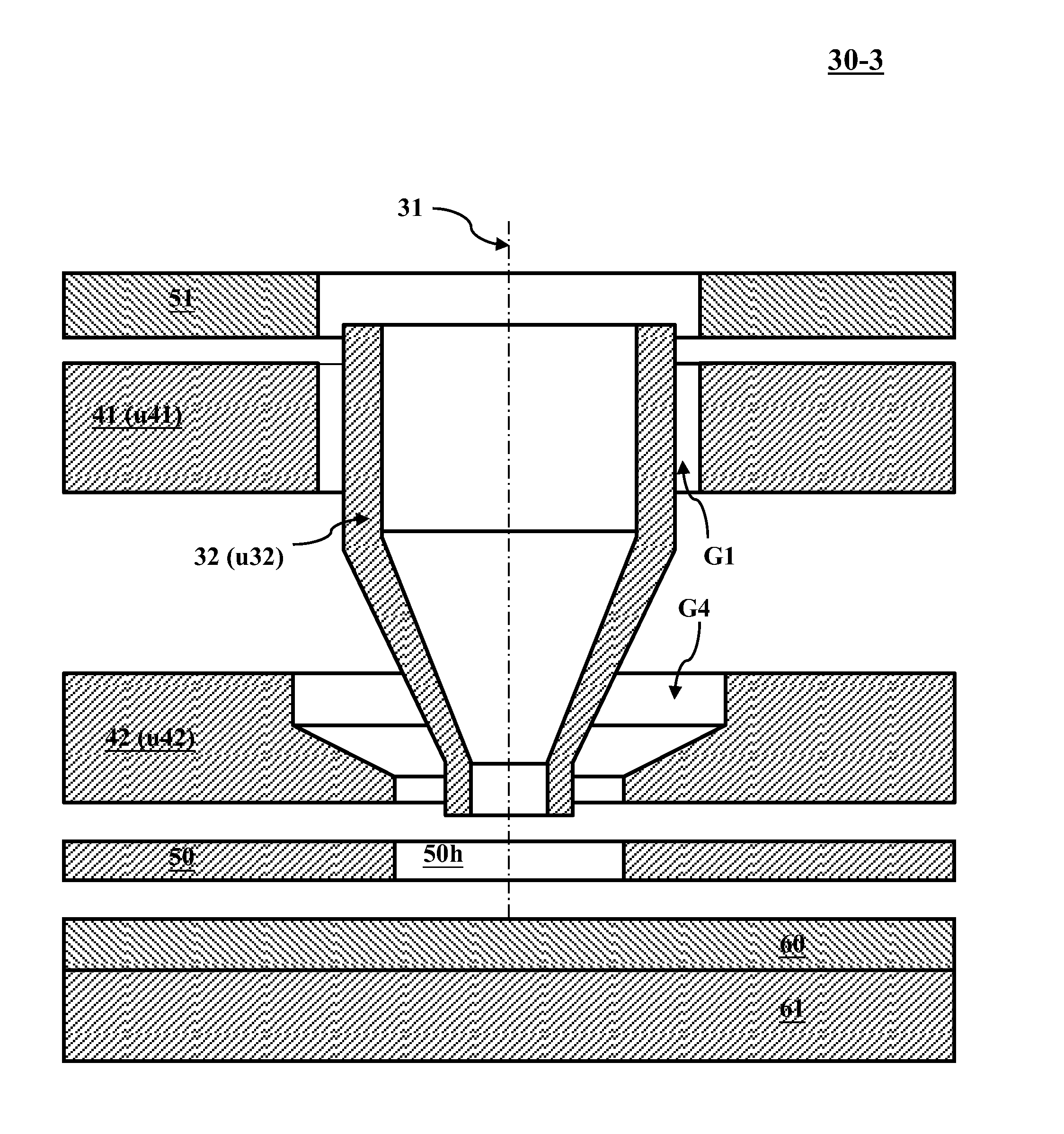
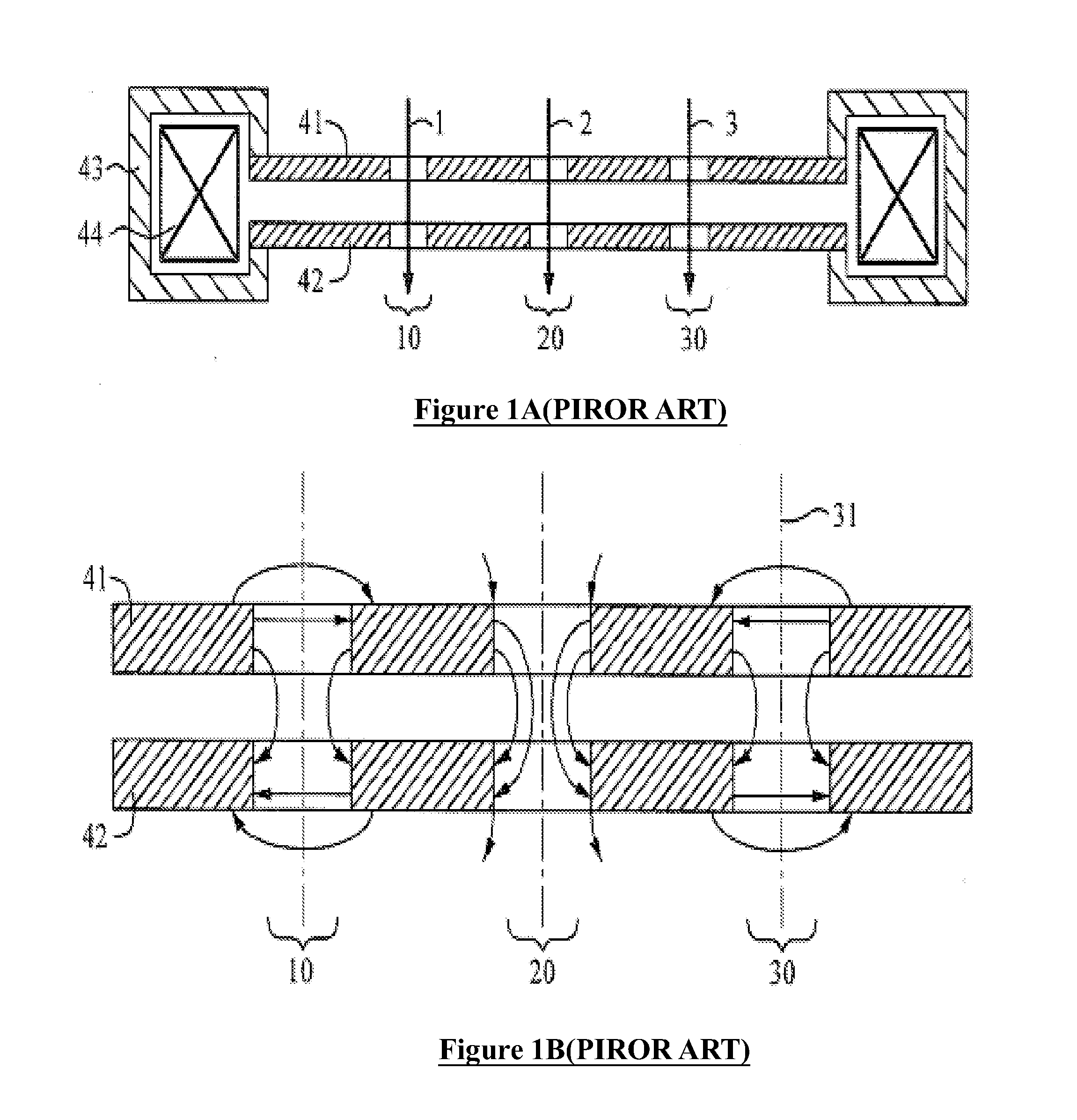
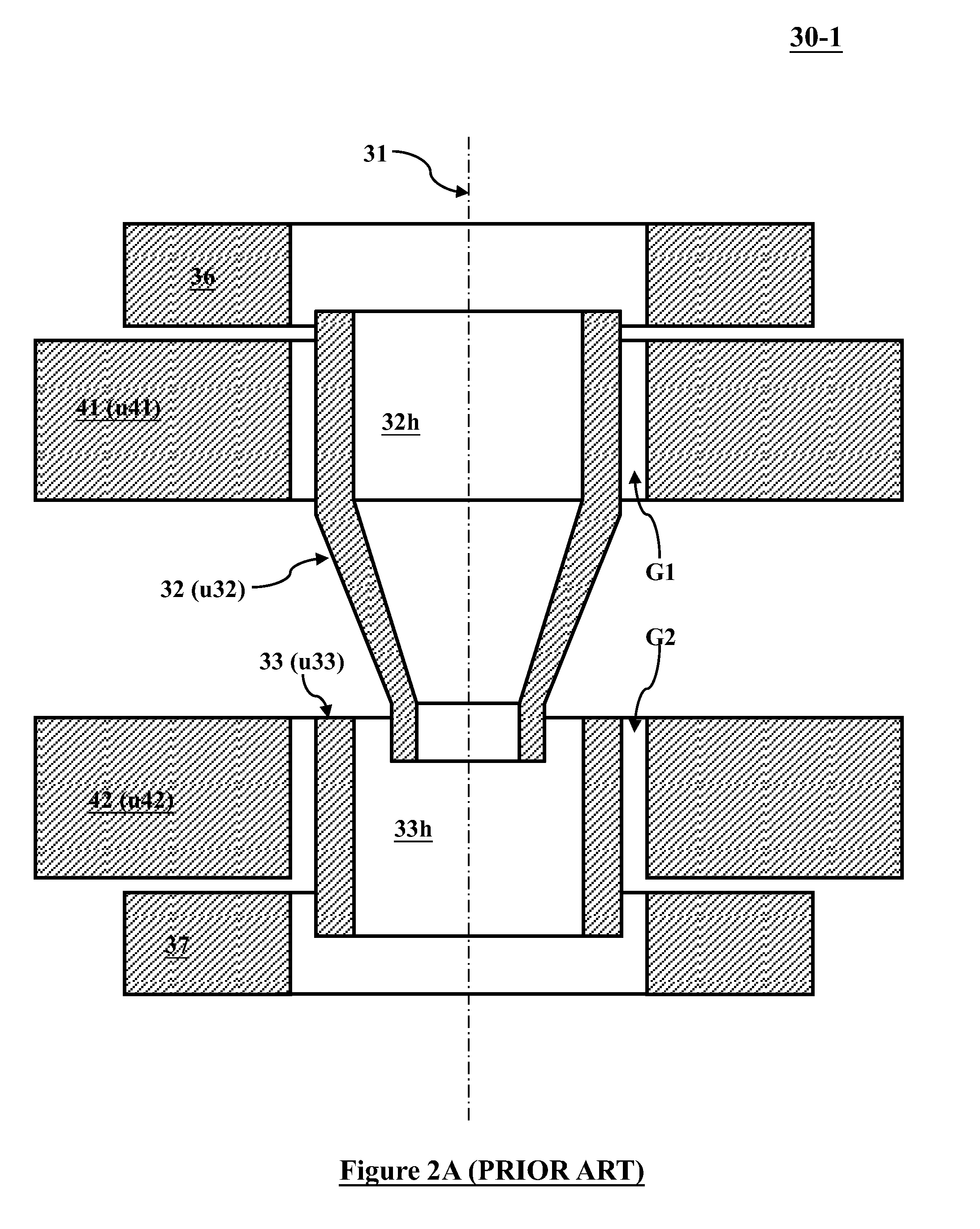
[0056]Various example embodiments of the present invention will now be described more fully with reference to the accompanying drawings in which some example embodiments of the invention are shown. Without limiting the scope of the protection of the present invention, all the description and drawings of the embodiments will exemplarily be referred to an electron beam. However, the embodiments are not be used to limit the present invention to specific charged particles.

[0057]In the drawings, relative dimensions of each component and among every component may be exaggerated for clarity. Within the following description of the drawings the same or like reference numbers refer to the same or like components or entities, and only the differences with respect to the individual embodiments are described.

[0058]Accordingly, while example embodiments of the invention are capable of various modifications and alternative forms, embodiments thereof are shown by way of example in the drawings and...


PUM

PropertyMeasurementUnit
magnetic fluxaaaaaaaaaa
magneticaaaaaaaaaa
permeabilityaaaaaaaaaa

Abstract

The present invention provides two ways to form a special permeability-discontinuity unit inside every sub-lens of a multi-axis magnetic lens, which either has a simpler configuration or has more flexibility in manufacturing such as material selection and mechanical structure. Accordingly several types of multi-axis magnetic lens are proposed for various applications. One type is for general application such as a multi-axis magnetic condenser lens or a multi-axis magnetic transfer lens, another type is a multi-axis magnetic non-immersion objective which can require a lower magnetomotive force, and one more type is a multi-axis magnetic immersion objective lens which can generate smaller aberrations. Due to using permeability-discontinuity units, every multi-axis magnetic lens in this invention can also be electrically excited to function as a multi-axis electromagnetic compound lens so as to further reduce aberrations thereof and / or realize electron beam retarding for low-voltage irradiation on specimen.

Description

CLAIM OF PRIORITY[0001]This application claims the benefit of priority of U.S. provisional application No. 61 / 577,888 entitled to Weiming et al. filed Dec. 20, 2011 and entitled “Multi-axis Magnetic Lens for Focusing a Plurality of Charged Particle Beams”, the entire disclosures of which are incorporated herein by reference.CROSS REFERENCE TO RELATED APPLICATIONS[0002]This application is related to co-pending U.S. application Ser. No. 12 / 968,221 entitled to Chen et al. filed Dec. 14, 2010 and entitled “APPARATUS OF PLURAL CHARGED PARTICLE BEAMS WITH MULTI-AXIS MAGNETIC LENS”, the entire disclosures of which are incorporated herein by reference.[0003]This application is also related to co-pending U.S. application Ser. No. 12 / 968,201 entitled to Chen et al. filed Dec. 14, 2010 and entitled “APPARATUS OF PLURAL CHARGED PARTICLE BEAMS WITH MULTI-AXIS MAGNETIC LENS”, the entire disclosures of which are incorporated herein by reference.BACKGROUND OF THE INVENTION[0004]1. Field of the Inve...

Claims


Application Information

Patent Timeline
Patent Type & Authority Applications(United States)
IPC IPC(8): H01J3/20H01F7/02
CPCH01J3/20H01J37/141H01J37/145H01J37/3177B82Y40/00H01J2237/1415H01J2237/31774B82Y10/00H01J2237/1035H01J37/14
Inventor REN, WEIMINGCHEN, ZHONGWEI
Owner ASML NETHERLANDS BV
Why Eureka
Try Eureka