
Structure for predominating light-emitting brightness or uniformization of light guide plate

A light guide plate, homogenization technology, applied in the direction of light guide, optics, optical components, etc., can solve the problems of enhancement and deficiency of local luminous brightness

Inactive Publication Date: 2011-05-11
SHANGHAI XIANGLONG ELECTRONICS TECH
View PDF2 Cites 8 Cited by
  • Summary
  • Abstract
  • Description
  • Claims
  • Application Information

AI Technical Summary

Problems solved by technology

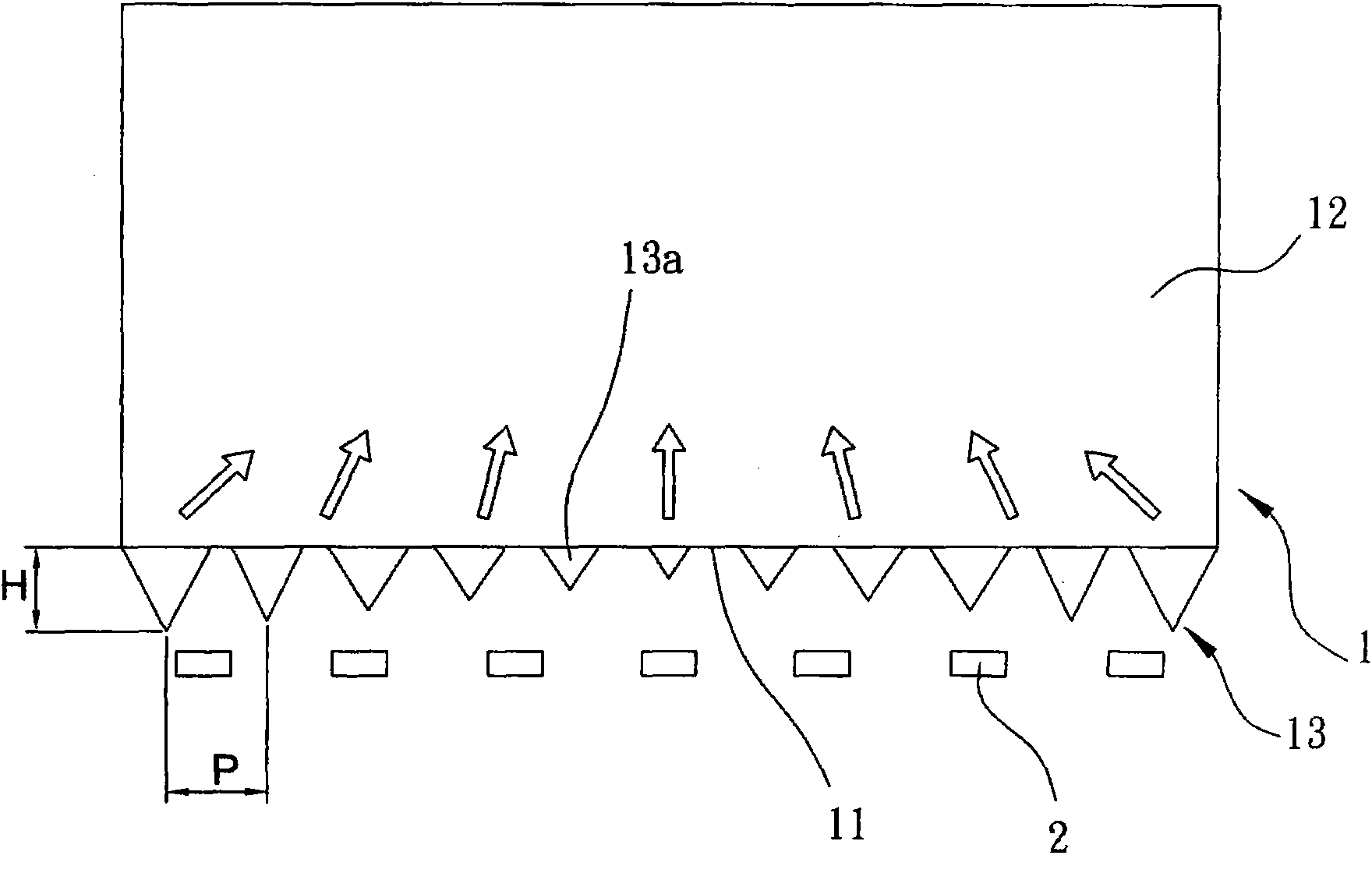
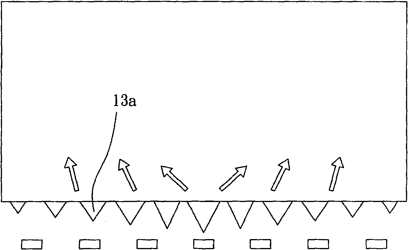
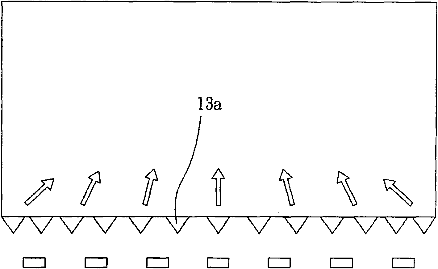
[0008] The aforementioned microstructures of the light incident surface of the light guide plate in the prior art generally have equal pitches and equal depths, which is of course helpful for the overall light emission uniformity of the light guide plate, but for obtaining local The enhancement of luminous brightness may be insufficient

Method used


Image

  • Structure for predominating light-emitting brightness or uniformization of light guide plate
  • Structure for predominating light-emitting brightness or uniformization of light guide plate
  • Structure for predominating light-emitting brightness or uniformization of light guide plate

Examples


Embodiment Construction

[0030] Below in conjunction with accompanying drawing and specific embodiment the present invention is described in further detail:

[0031] The main purpose of the present invention is to improve the microstructure of the light-incoming surface of the light guide plate of the existing backlight module, so that the light-emitting surface of the light guide plate can not only obtain a uniform luminous effect, but also can be adjusted by the pitch or depth of the microstructure. Different luminance effects are produced locally on the light guide plate due to the change of the light guide plate.

[0032] The feature of the present invention is that the microstructures arranged on the light incident surface of the light guide plate are set to have different pitches or / and depths according to the brightness requirements of the light exit surface of the light guide plate, so that light can penetrate the microstructures After entering the light guide plate, the reflection and refract...


PUM


Abstract

The invention relates to a structure for predominating the light-emitting brightness or the uniformization of a light guide plate. A plurality of microstructures are arranged on a light incident surface of the light guide plate, so that light penetrates through the microstructures to enter the light guide plate; with the reflection or refraction of the light, the brightness in a specific area of the light guide plate can be improved or the light emitting of the light guide plate is uniformized; the microstructures can be objects protruded from the light incident surface of the light guide plate or concave parts lower than the light incident surface; a pitch is formed between two protruded objects and two concave parts; each protruded object or concave part is provided with a height or a concave part; and the pitch is matched with the height or the concave part to change according to the brightness degree to be acquired by the light guide plate so as to generate different amount of light entering the light guide plate.

Description

technical field [0001] The invention relates to a backlight module, in particular to a light guide plate structure applied to the backlight module. Background technique [0002] The application of backlight modules is very common. For example, electronic devices such as notebook computers, monitors, mobile phones, LCD TVs, etc., which do not emit light by themselves, require backlight modules to provide light sources. [0003] A general backlight module includes a light guide plate and a light source. For electronic products that require a thin body, LEDs are usually used as the light source, and the light source is placed on the light incident surface on the side of the light guide plate. One side is provided with a reflective sheet, and the opposite second side is used as a light-emitting surface and is provided with a plurality of optical films composed of a diffusion sheet and an enhancement sheet. The light emitted by the light source is projected into the light guide ...

Claims


Application Information

Patent Timeline
Patent Type & Authority Applications(China)
IPC IPC(8): F21V8/00
Inventor 张俊彬曾国柱温明晃
Owner SHANGHAI XIANGLONG ELECTRONICS TECH
Learn More