Eureka AIR delivers breakthrough ideas for toughest innovation challenges, trusted by R&D personnel around the world.

Quick clamping device

A fast, curvilinear technique

Inactive Publication Date: 2011-05-11
XIAN HUANIC OPTOELECTRONICS CORP
View PDF7 Cites 11 Cited by
  • Summary
  • Abstract
  • Description
  • Claims
  • Application Information

AI Technical Summary

Problems solved by technology

[0004] The purpose of the present invention is to provide a non-linear curve eccentric cam type fast clamping device, which solves the problems of slow installation, complicated operation and low efficiency of the existing clamping device

Method used


Image

  • Quick clamping device
  • Quick clamping device
  • Quick clamping device

Examples


Embodiment Construction

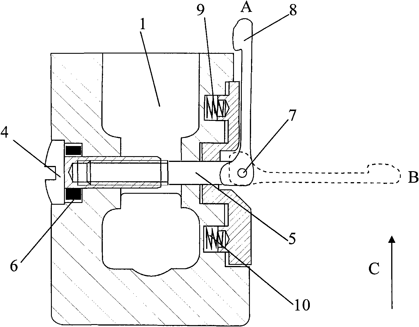
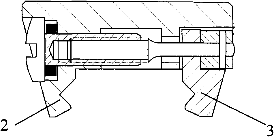
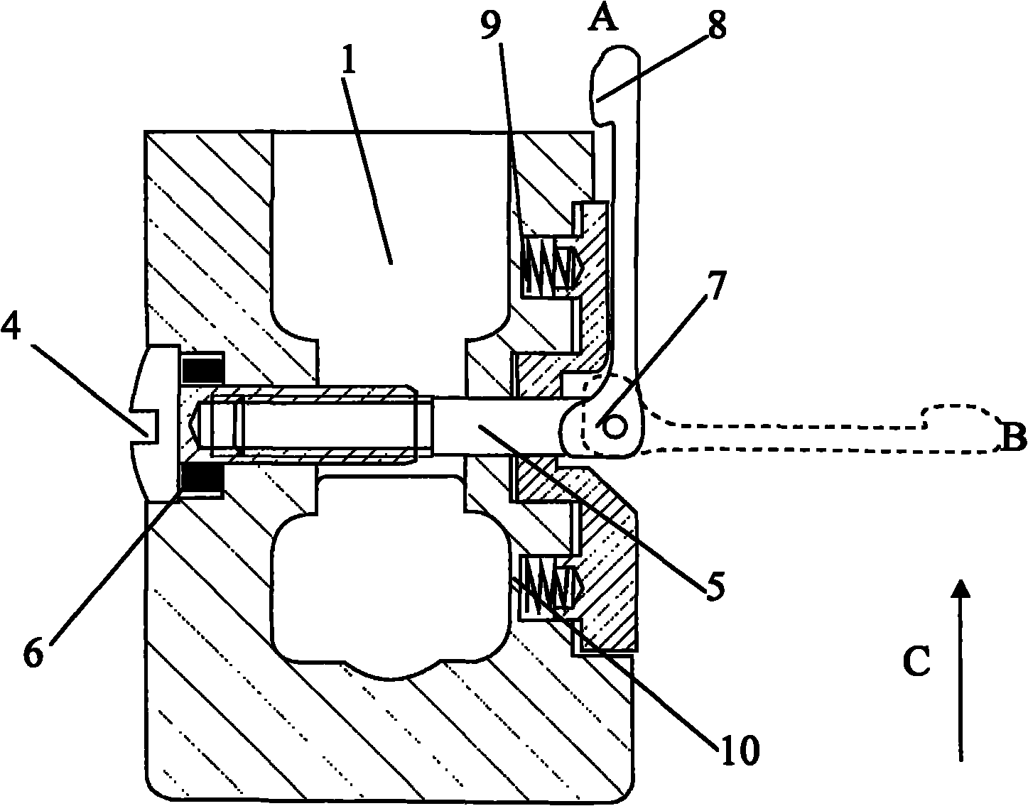
[0010] see figure 1 , 2 , the implementation device of the present invention includes: body 1, fixed slot 2, movable slot 3, pull rod sleeve 4, pull rod shaft 5, butterfly spring 6, latch 7, nonlinear curve eccentric cam handle 8, tension spring 9, 10 composition. Wherein the fixed card slot 2 and the movable card slot 3 are arranged at the lower end of the body 1 . The pull rod sleeve 4 is arranged in the middle hole of the fixing slot 2 , one end is arranged outside the fixing slot 2 , and the other end is screwed to one end of the pull rod shaft 5 . A butterfly spring 6 is arranged between one end of the pull rod sleeve 4 and the fixing slot 2 . The other end of the pull rod shaft 5 is set in the hole in the middle of the movable card slot 3 , extends to the outside of the movable card slot 3 , and is connected with the non-linear curve eccentric cam handle 8 through the latch 7 . Tension springs 9 and 10 are respectively arranged between the two ends of the movable car...


PUM


Abstract

The invention relates to a nonlinear curve eccentric cam type quick clamping device. When a handle of a nonlinear curve eccentric cam is closed, the eccentric cam reaches a highest point to realize a clamping function; the curve surface of the cam is a nonlinear curve surface, and a self-locking and anti-falling function is realized; when a spanner is pulled, the eccentric cam reaches a lowest point, and under the action of a tension spring, a fixed slip groove and a movable slip groove are loosened. In the invention, the clamping force is regulated through regulating the connecting threads of a pull rod sleeve and a pull rod shaft, thus the eccentric cam can be used for realizing the functions of quickly assembling and disassembling, quickly clamping, self-locking and preventing loosening. The eccentric cam has the advantages of compact structure, small size, light weight, convenience for operation, and the like and solves the problems of slower mounting, complicated operation and low efficiency of the traditional clamping device.

Description

technical field [0001] The invention relates to a clamping device, in particular to a nonlinear curve eccentric cam type quick clamping device. Background technique [0002] At present, sights, front handles of rifles, etc. are mostly installed by screw tension, and generally need to be equipped with accessories such as wrenches. In actual use, not only is it inconvenient to carry, but also time-consuming and laborious to install and disassemble. There is also a quick clamping through the friction force of the inclined plane, which is actually equivalent to increasing the pitch of the thread. It also requires auxiliary tools to achieve clamping, and the actual efficiency is not high. [0003] In addition, in other similar guide rail installations, screw tensioning installations or screw compression installations are generally used, and accessories such as wrenches must be equipped with tools such as wrenches. The installation is slow, and tools need to be carried at any time...

Claims


Application Information

Patent Timeline
Patent Type & Authority Applications(China)
IPC IPC(8): F41G1/28
Inventor 孙建华
Owner XIAN HUANIC OPTOELECTRONICS CORP
Why Eureka
Eureka Blog
Learn More