Supercharge Your Innovation With Domain-Expert AI Agents!

USB special charger recognition circuit

A technology for identifying circuits and chargers, applied in passive battery identification, battery circuit devices, collectors, etc., can solve problems such as complex circuits and algorithms

Active Publication Date: 2015-04-15
MAXIM INTEGRATED PROD INC
View PDF4 Cites 0 Cited by
  • Summary
  • Abstract
  • Description
  • Claims
  • Application Information

AI Technical Summary

Problems solved by technology

Second, decisions must be made based on current thresholds
Third, as the device iterates through different possible modes, V BUS must be repeatedly turned off and on
The circuits and algorithms proposed by Fairchild are thus complicated

Method used


Image

  • USB special charger recognition circuit
  • USB special charger recognition circuit
  • USB special charger recognition circuit

Examples


Embodiment Construction

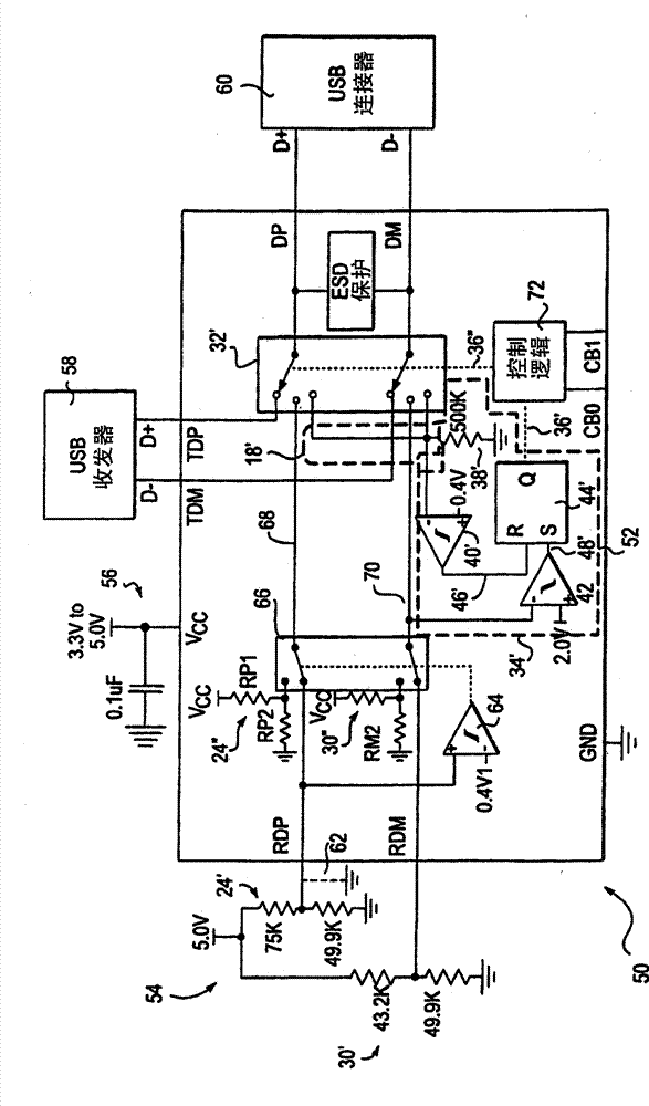
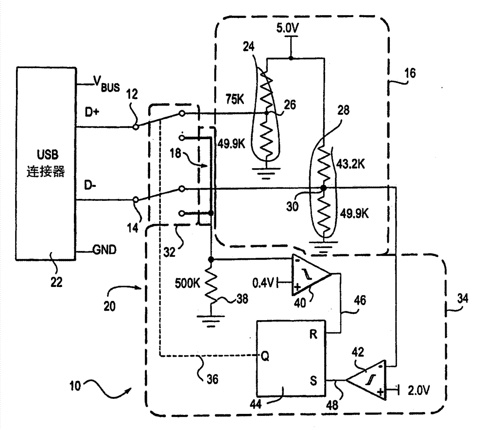
[0025] 1-4 are described with reference to the prior art. Figure 5 In, the implementation of the USB special charger identification circuit 10 is shown by way of example and not limitation, including a USB D+ port 12, a USB D- port 14, a first circuit 16 conforming to the first identification protocol, and a first circuit 16 conforming to the second identification protocol for the second circuit 18 . USB specific charger 10 also includes logic 20 configured to selectively couple one of first circuit 16 and second circuit 18 to USB D+ port 12 and USB D− port 14 . Figure 5 Also shown is a USB connector 22 which does not form part of the USB-specific charger identification circuit 10 .

[0026] In this embodiment, the USB connector 22 has four contacts. two contacts, namely V BUS and GND are used to provide power. The other two contacts, namely D+ contact and D- contact are used to carry data. Such as Figure 5As shown, the D+ contact is coupled to the D+ port 12 of the U...


PUM


Abstract

The circuit has a circuit unit comprising a voltage divider i.e. conductor, coupled with another voltage divider in parallel. An electronic switch is provided with two poles. The electronic switch couples another circuit unit and the former circuit unit to a universal serial bus (USB)D+ port and a USBD- port. Independent claims are also included for the following: (1) a method for providing universal serial bus charger identification (2) a universal serial bus charger identification device.

Description

Background technique [0001] The Universal Serial Bus ("USB") was designed to provide a serial communication channel between computers and peripheral devices. For example, USB is capable of connecting computer peripherals like mice, keyboards, game pads, joysticks, scanners, external drives, etc. to a computer. When USB was designed for personal computers, it became a common accessory for battery-powered computerized devices like PDAs, music players, and mobile phones, which utilized USB for data communication and to recharge their batteries. The design of USB is standardized by the USB Design Forum (USBIF), which is the body of industry standards including leading companies from the computer and electronics industries. [0002] Several types of USB connectors certified by USBIF include four-contact (pin or receptacle) connectors like the USB-A and USB-B connectors, and connectors like the Mini / Micro-A, Mini / Micro-B, and five-contact (pin or socket) connectors like the Mini / M...

Claims


Application Information

Patent Timeline
Patent Type & Authority Patents(China)
IPC IPC(8): H02J7/00
CPCH02J7/0006H02J7/0042H02J2007/0062G06F1/266H02J7/00038H02J7/00047H02J7/00
Inventor K·赫尔弗里赫
Owner MAXIM INTEGRATED PROD INC
Features
  • R&D
  • Intellectual Property
  • Life Sciences
  • Materials
  • Tech Scout
  • Unparalleled Data Quality
  • Higher Quality Content
  • 60% Fewer Hallucinations
Learn More