
Connector

A technology for connectors and connection objects, which is applied in the direction of connection, parts of connecting devices, devices for preventing wrong connection, etc.

Inactive Publication Date: 2011-05-11
IRISO ELECTRONICS CO LTD
View PDF6 Cites 9 Cited by
  • Summary
  • Abstract
  • Description
  • Claims
  • Application Information

AI Technical Summary

Problems solved by technology

[0006] However, in the aforementioned connector, even if the lock member is displaced upward due to incomplete insertion of the flexible circuit, since the pressing member can be rotated to the locked position, incomplete insertion cannot be confirmed visually based on the lock member. , the pressing member is closed without being fully inserted to complete the connection with the flexible circuit, and there is a problem that it is impossible to reliably prevent poor connection by visual confirmation

Method used


Image

  • Connector
  • Connector
  • Connector

Examples


Embodiment Construction

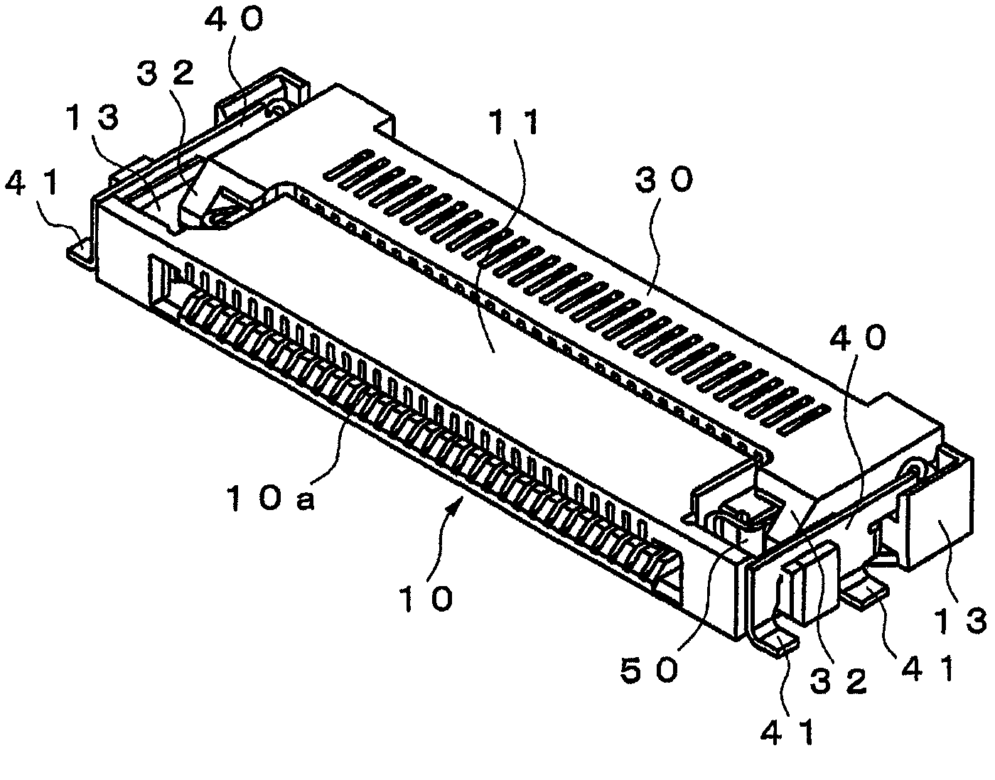
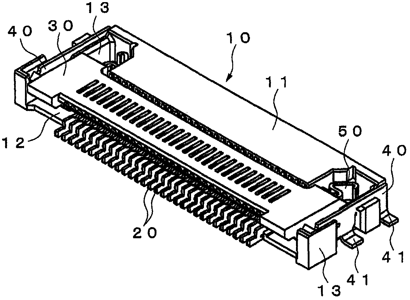
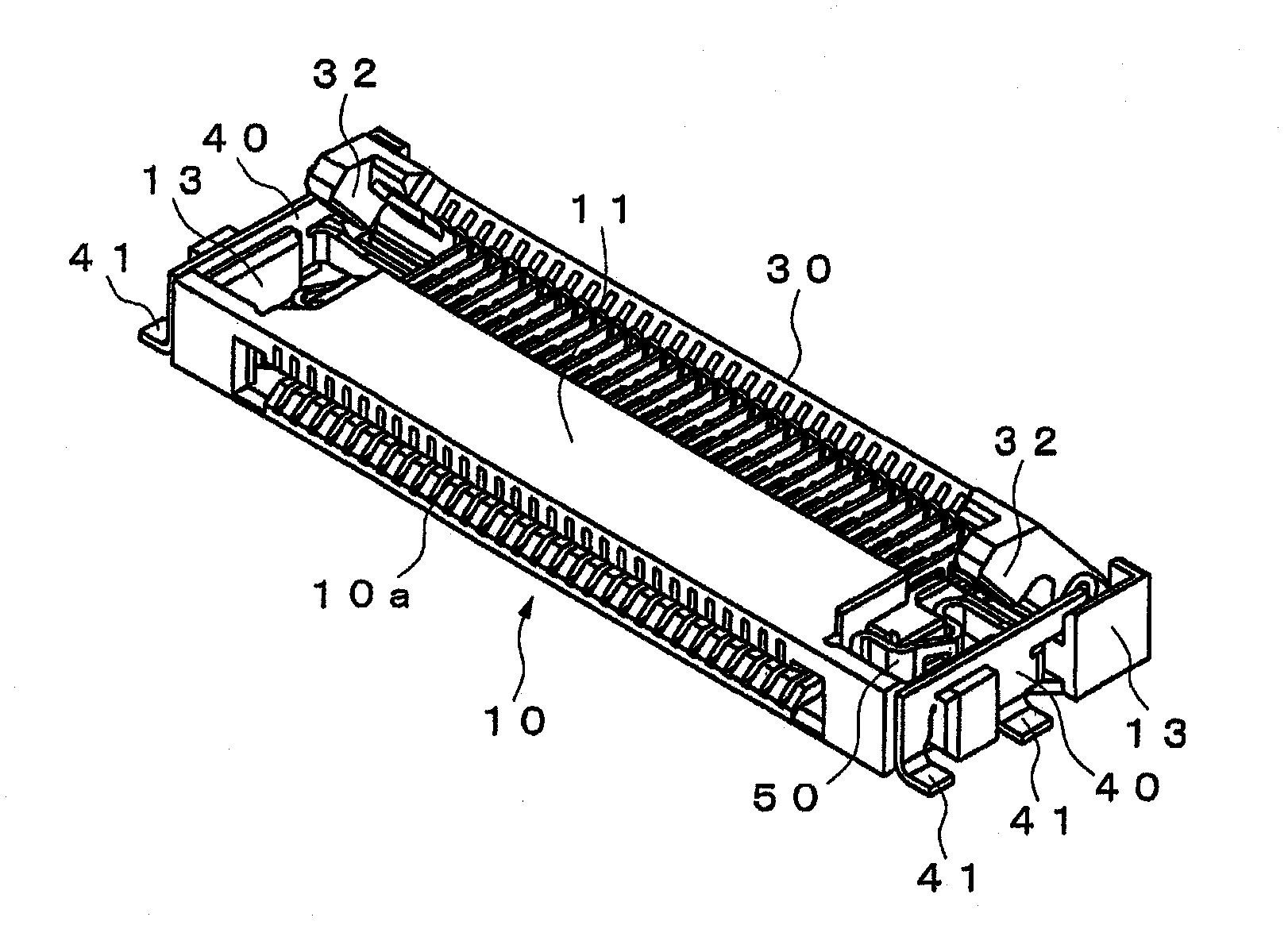
[0029] Figure 1 to Figure 11 An embodiment of the present invention is shown. The connector shown in this figure includes: a connector body 10 inserted into a flexible circuit 1 as a connection object; a plurality of terminals 20 arranged at intervals in the width direction in the connector body 10; 20 is a rotatable pressing member 30 that presses the side of the flexible circuit 1 inserted into the connector body 10; a pair of left and right fixing members 40 for fixing the connector body 10 to an unshown substrate; and the flexible circuit 1 A pair of locked left and right lock members 50 .

[0030] The flexible circuit 1 includes a so-called flexible flat cable (FFC) or flexible printed circuit (FPC), and a plurality of electrical connection points (not shown) are provided on the surface above the front end side at intervals in the width direction. . In addition, at both ends in the width direction of the flexible circuit 1 are provided notches 1 a as engaging portions...


PUM


Abstract

A connector capable of effectively preventing a connection failure due to incomplete insertion of an object which is connected to the connector. When the front end of a flexible circuit (1), which is inserted in the connector body (10), makes contact with a lock member (50) and when a pressing member (30) is then pivoted in one direction with the lock member (50) deformed to the outside in the width direction of the connector body (10), a protrusion (32) of the pressing member (30) makes contact with the lock member (50) to restrict the rotation of the pressing member (30), and when the pressing member (30) is pivoted in said direction with the lock member (50) returned to the inside in the width direction of the connector body (10), the pressing member (30) is permitted to rotate. The configuration prevents the pressing member (30) from pivoting to a closed position with the flexible circuit (1) incompletely inserted, and this effectively prevents a connection failure due to the incomplete insertion of the flexible circuit (1).

Description

technical field [0001] The present invention relates to a connector for connecting a flexible printed circuit (FPC) and / or a flexible flat cable (FFC) or the like. Background technique [0002] Conventionally, as this type of connector, there is known a structure including the following parts: a connector body that can be inserted into one end of a connection object such as FPC and / or FFC (hereinafter referred to as a flexible circuit) on the front side; a plurality of terminals on the connector body; and a rotatable pressing member for pressing a flexible circuit inserted into the connector body toward each terminal (for example, refer to Patent Document 1). [0003] This connector is configured such that when the pressing member is rotated in the locking direction with the flexible circuit inserted into the connector body, the flexible circuit and each terminal are crimped by the pressing member to conduct mutual conduction. direction, the crimping between each terminal a...

Claims


Application Information

Patent Timeline
Patent Type & Authority Applications(China)
IPC IPC(8): H01R13/64H01R12/77H01R13/639
CPCH01R12/79H01R12/88H01R12/592H01R12/707
Inventor 小椋由幸吉开靖芳
Owner IRISO ELECTRONICS CO LTD
Learn More