Low-heart position underwear heart position supporting frame
A support frame and heart position technology, applied in corsets, clothing, belts, etc., can solve problems such as limited heart position, and achieve the effect of ensuring comfort, ensuring aesthetic effect, and simple structure
- Summary
- Abstract
- Description
- Claims
- Application Information
AI Technical Summary
Problems solved by technology
Method used
Image
Examples
Embodiment 1
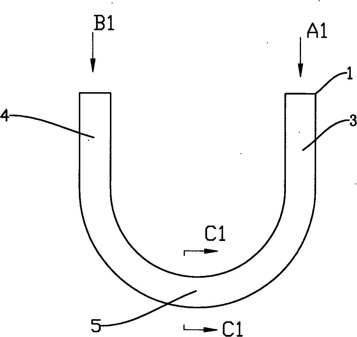
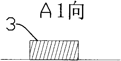
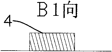
[0035] Example 1, such as figure 1 , figure 2 , image 3 , Figure 4 and Figure 5 as shown in:
[0036] In order to achieve the purpose of the present invention, the support frame body 1 is a U-shaped support frame, and the blank structure of the support frame body 1 is a wide and flat wire; the support frame body is a U-shaped support frame, The blank structure of the support frame body is a wide and flat wire; the wire planes of the two vertical parts of the support frame body correspond to a twist angle with the vertical axis, and the starting position of the twist is U The zero boundary point 2 of the arc and the vertical part of the U-shape constitutes a U-shaped support frame in which the U-shaped arc part is a plane and the vertical part corresponds to the arc part plane and is another plane at a torsion angle. ; The included angle between the twisted wire plane and the horizontal plane is: 0°-85°. In this example, if figure 2 , image 3 , Figure 4 As shown...
Embodiment 2
[0038] Example 2, such as Figure 6 , Figure 7 , Figure 8 , Figure 9 and Figure 10 as shown in:
[0039] In this embodiment, the wire planes 31 and 41 of the two vertical parts of the support frame body are twisted outward respectively, and the starting position of the twist is the zero boundary point 21 between the U-shaped arc and the vertical part, The arc part constituting the U-shape is a plane 51, and the wire rod planes 31, 41 of the two vertical parts are U-shaped support frames opposite to each other; The angle is 30°. Such as Figure 7 , Figure 8 , Figure 9 As shown in , the angle of rotation between the wire plane 31 of the vertical part and the horizontal plane from A2 is 30° clockwise, while the rotation angle of the wire plane 41 and the horizontal plane of the vertical part from B2 is counterclockwise 30°. In this structure, the cross-sectional view of the plane 51 of the U-shaped arc portion at C2-C2 shows that the rotation angle between the pla...
Embodiment 3
[0043] Example 3, such as Figure 11 , Figure 12 , Figure 13 , Figure 14 and Figure 15 as shown in:
[0044] The cross-sectional shape of the wide and flat wires of the support frame body described in this embodiment is trapezoidal; the wire planes 32 and 42 of the two vertical parts of the support frame body are respectively twisted outward, and the starting position of the twist is The zero boundary point 22 of the U-shaped arc and the vertical part constitutes the U-shaped arc part as a plane 52, and the wire rod planes 32, 42 of the two vertical parts are U-shaped support frames of opposite planes; The angle between the outwardly twisted wire planes 32, 42 and the horizontal plane is 85°. Such as Figure 7 , Figure 8 , Figure 9As shown in , the angle of rotation between the wire plane 32 of the vertical part and the horizontal plane from A3 is 85° clockwise, while the rotation angle of the wire plane 42 and the horizontal plane of the vertical part from B3 is...
PUM
 Abstract
Description
Claims
Application Information
 - R&D
- Intellectual Property
- Life Sciences
- Materials
- Tech Scout
- Unparalleled Data Quality
- Higher Quality Content
- 60% Fewer Hallucinations
Browse by: Latest US Patents, China's latest patents, Technical Efficacy Thesaurus, Application Domain, Technology Topic, Popular Technical Reports.
© 2025 PatSnap. All rights reserved.Legal|Privacy policy|Modern Slavery Act Transparency Statement|Sitemap|About US| Contact US: help@patsnap.com


