
Treatment method of drainage pipe pile composite foundation

A technology for drainage pipe piles and a treatment method, which is applied in basic structure engineering, soil protection, construction and other directions, can solve problems such as broken piles, pile body inclination, prolonged construction period, unfavorable engineering construction, etc. The effect of project cost and simple construction

Inactive Publication Date: 2011-05-18
GUANGDONG PROVINCE HANGSHENG CONSTR GRP
View PDF2 Cites 4 Cited by
  • Summary
  • Abstract
  • Description
  • Claims
  • Application Information

AI Technical Summary

Problems solved by technology

[0002] With the continuous shortening of the construction period of highways and railways, the allowable post-construction settlement is getting smaller and smaller, but the construction of pipe piles in the cohesive soil foundation will generate excess static pore water pressure in the foundation, resulting in lateral displacement or ground uplift , it may cause engineering accidents such as broken piles and pile body inclination, which will have an adverse impact on engineering construction. There is excess static pore water pressure in the soil, if no vertical drainage body is set between the piles, the settlement of the foundation after construction may be relatively large
[0003] In order to avoid or reduce the above adverse effects, it is usually necessary to set up vertical drainage bodies in the foundation first, and adopt measures such as pile jumping construction technology, which makes the construction technology complicated, the project cost is high, and the construction period is lengthened

Method used


Image

  • Treatment method of drainage pipe pile composite foundation
  • Treatment method of drainage pipe pile composite foundation
  • Treatment method of drainage pipe pile composite foundation

Examples


Embodiment 1

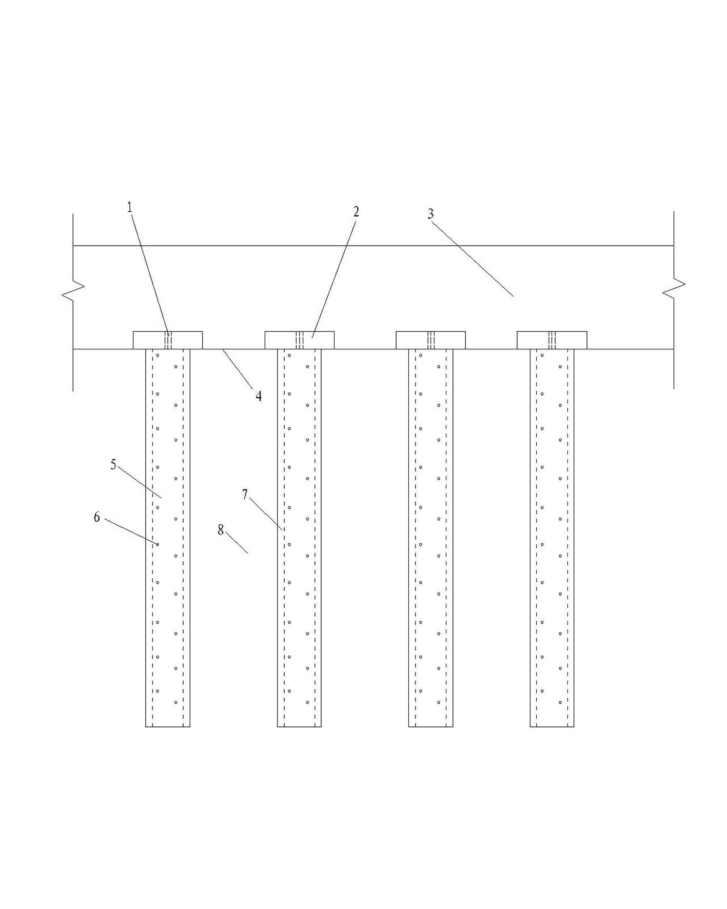
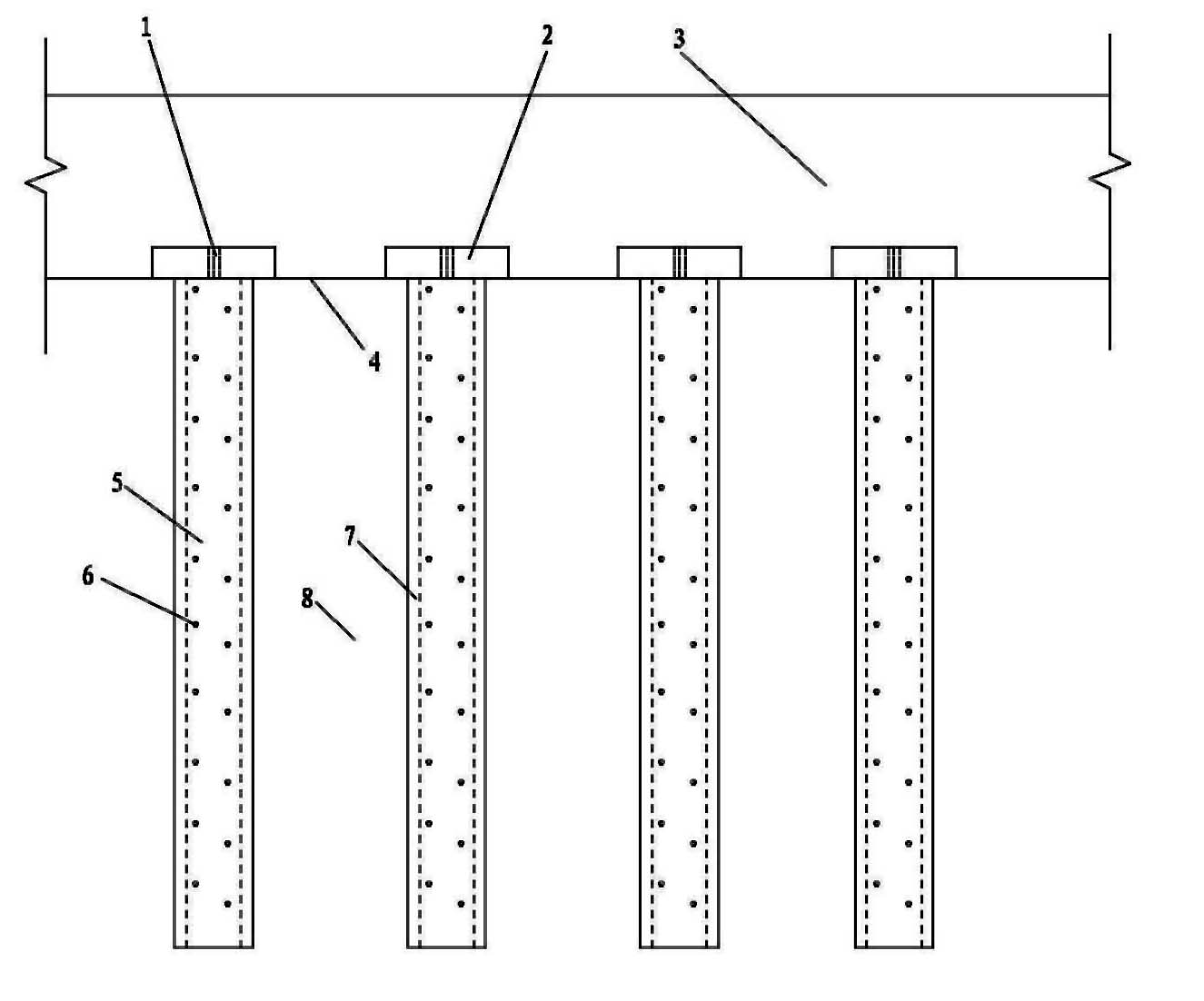
[0024] A drainage pipe pile composite foundation treatment method, comprising the following steps:

[0025] (1) First set a certain number of small holes through the pipe wall on the pipe wall of the drainage pipe pile;

[0026] (2) Then arrange the drainage pipe piles with small holes at a certain interval in the soft clay foundation;

[0027] (3) Finally, set a pile cap on the top of the drainage pipe pile, set a reserved hole on the pile cap, set a drainage cushion on the top surface of the pile cap, apply a load to the drainage cushion, and the groundwater in the soil between the piles passes through the drainage pipe pile The small hole on the wall flows into the pile hole of the drainage pipe pile, and is discharged through the reserved hole on the pile cap and the drainage cushion.

Embodiment 2

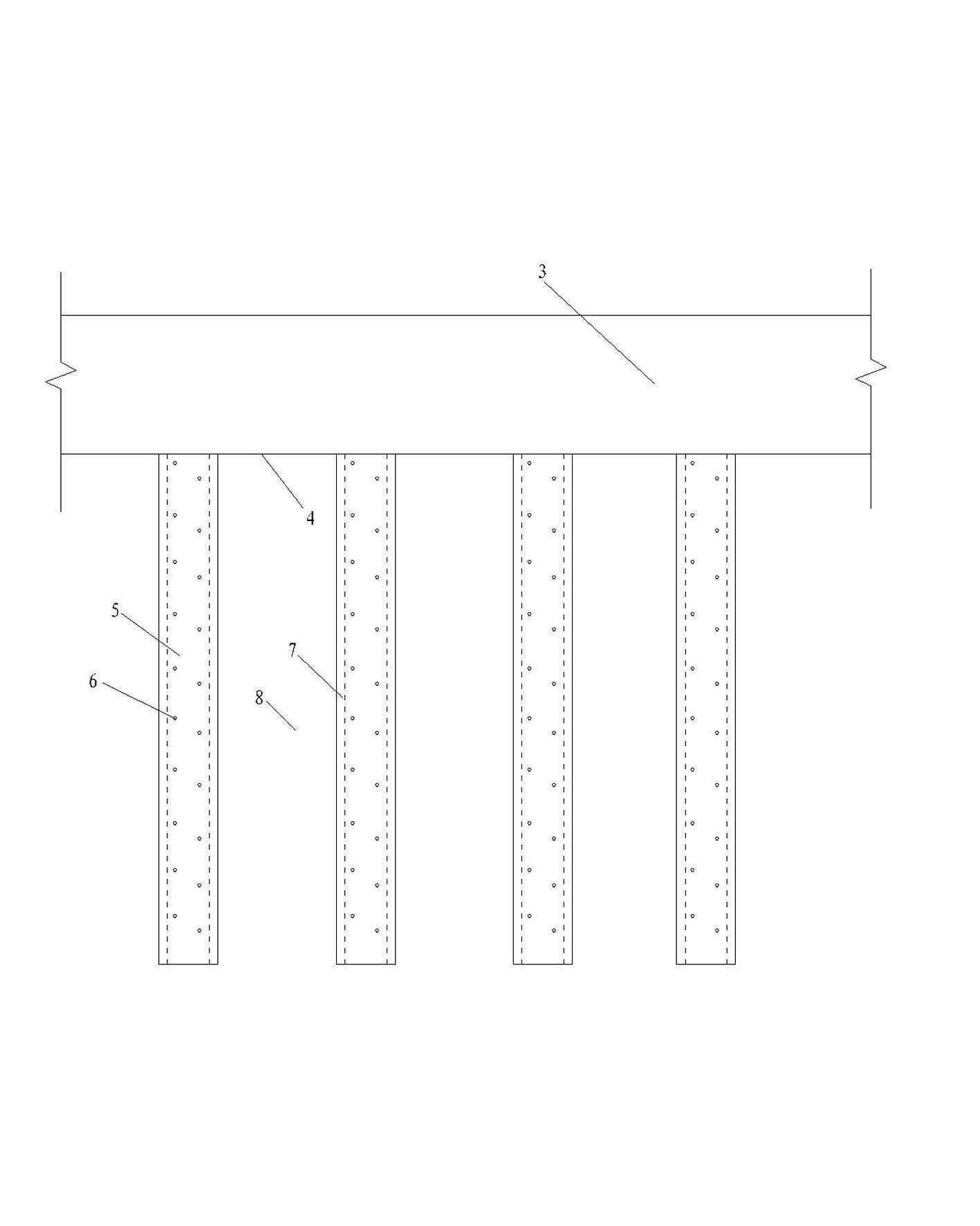
[0029] A drainage pipe pile composite foundation treatment method, comprising the following steps:

[0030] (1) First set a certain number of small holes through the pipe wall on the pipe wall of the drainage pipe pile;

[0031] (2) Then arrange the drainage pipe piles with small holes at a certain interval in the soft clay foundation;

[0032] (3) Finally, a drainage cushion is set on the top surface of the drainage pipe pile, and a load is applied on the drainage cushion. row away.


PUM


Abstract

The invention relates to a treatment method of a drainage pipe pile composite foundation. The treatment method comprises the following steps: arranging drainage pipe piles according to a certain distance in a soft clay foundation; arranging drainage cushion layers on the top surfaces of the drainage pipe piles or pile caps; when the pile caps are arranged on the top of the drainage pipe piles, arranging preformed holes on the pile caps so as to ensure that the pipe pile holes are communicated with the drainage cushion layers; and arranging a certain number of small holes penetrating through pipe walls on the pipe walls of the drainage pipe piles so that underground water in soil among the piles can flow into the pipe pile holes via the small holes and then is drained via the preformed holes and the drainage cushion layers on the pile caps. Therefore, by means of the treatment method of the drainage pipe pile composite foundation, the dissipation of excess pore water pressure in the soil among the piles can be enhanced, the soil compacting effect generated by pipe pile construction can be reduced, and the load carried by the soil among the piles or post-construction settlement caused by self weight of foundation soil can be reduced.

Description

technical field [0001] The invention relates to a foundation treatment method, in particular to a foundation treatment method capable of accelerating the dissipation of super-static pore water pressure in the foundation, and belongs to the technical field of foundation treatment. Background technique [0002] With the continuous shortening of the construction period of highways and railways, the allowable post-construction settlement is getting smaller and smaller, but the construction of pipe piles in the cohesive soil foundation will generate excess static pore water pressure in the foundation, resulting in lateral displacement or ground uplift , it may cause engineering accidents such as broken piles and pile body inclination, which will have an adverse impact on engineering construction. There is excess static pore water pressure in the soil. If no vertical drainage body is installed between the piles, the settlement of the foundation after construction may be relatively...

Claims


Application Information

Patent Timeline
Patent Type & Authority Applications(China)
IPC IPC(8): E02D3/10
Inventor 刘吉福徐小庆谭祥韶薜威许发明
Owner GUANGDONG PROVINCE HANGSHENG CONSTR GRP
Learn More