Method for designing section height sequence of structural steel sheared by hot rolling flying shears

A technology with a high degree of sequence and design method, applied in the field of metallurgical hot rolling technology, can solve problems such as unfavorable economical design, inconvenient product serialization design, and increased project operating costs

Inactive Publication Date: 2011-05-18
WISDRI ENG & RES INC LTD
View PDF1 Cites 10 Cited by
  • Summary
  • Abstract
  • Description
  • Claims
  • Application Information

AI Technical Summary

Problems solved by technology

As a result, the selected motor power may be too large or cannot meet the process and control requirements of the process for the shearing process
In addition, because in the accounting process, only one of the specifications is often calculated based on experience, there is a lack of systematic design verification methods and design means, which is not convenient for serialized design of products
Judging from the current actual engineering design, the motor is often much larger than the actual need, which virtually increases the cost of project operation, which is not conducive to economical design

Method used


Image

  • Method for designing section height sequence of structural steel sheared by hot rolling flying shears
  • Method for designing section height sequence of structural steel sheared by hot rolling flying shears
  • Method for designing section height sequence of structural steel sheared by hot rolling flying shears

Examples


Embodiment Construction

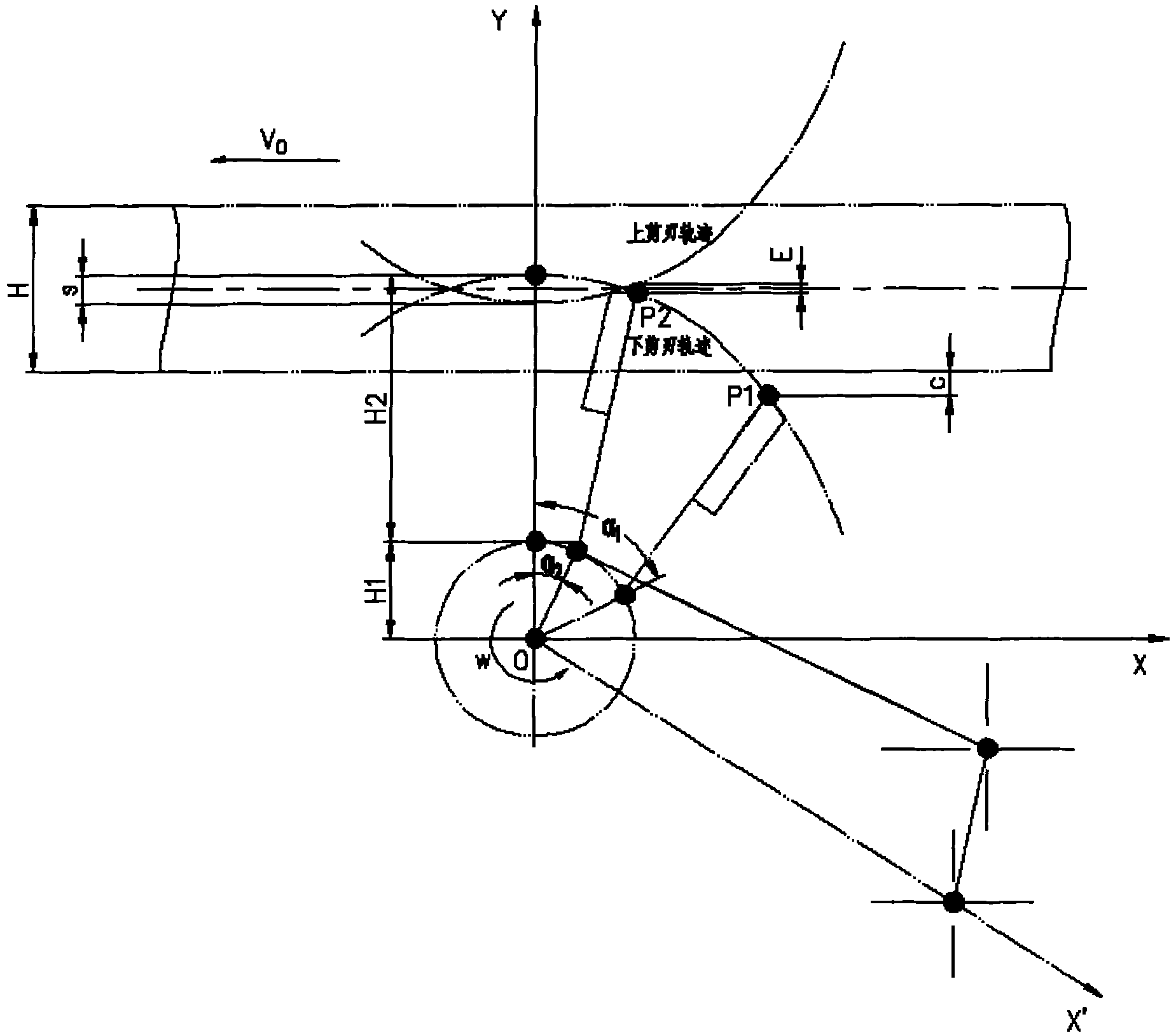
[0048] 1. The logical expression of the parameters required for the space trajectory of the cutting edge of the flying shear

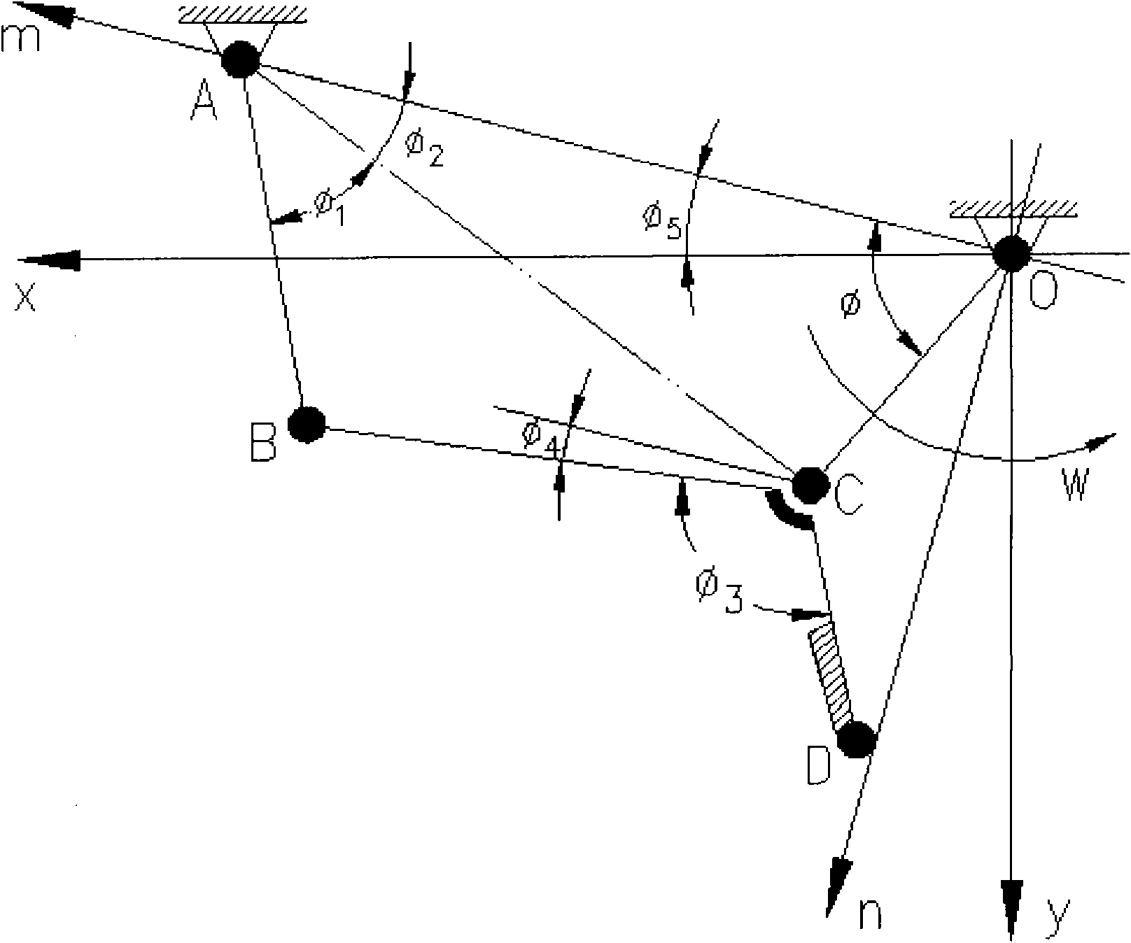
[0049] The original drawing of the upper cutting edge of the flying shear (the lower cutting edge is symmetrical to the rolling center line), as shown in figure 1 shown.

[0050] It is composed of connecting rod OC, rod AB and rod BCD: the rod BCD is welded by rod BC and rod CD, and the upper cutting edge is connected with the connecting rod CD through the blade seat. The crank OC is driven by a motor to make periodic revolving motions around its center of rotation O. It drives the connecting rod BCD and the upper cutting edge to move along the predetermined track through the hinge pair. One end B of the connecting rod BCD is connected with the rocker AB through a joint, and the rocker AB moves around the point A within a certain range. Before starting to cut, the upper cutting edge of the flying shear will stay at a specified position and form a ce...


PUM


Abstract

The invention relates to the technical field of metallurgical hot rolling process, and particularly discloses a method for designing a section height sequence of structural steel sheared by hot rolling flying shears, which comprises the following steps of: calculating a space trace curve of shearing blades; calculating theoretical coordinate values of the shearing blades; calculating a shear angle; performing translation on the output rotating speed of a motor, and the like; and finally determining judgment criterion for the selection of the motor and the rotating speed in systematic checking calculation to be that a relative difference between the output rotating speeds of the motor before and after the shearing may be not more than 25 percent and not less than 10 percent, determining that the designed section heights of the structural steel meet design requirements after the motor and the rotating speed reach the judgment criterion in a given section height designing range of the structural steel, and sequentially recording the designing values to obtain the section height sequence of the structural steel sheared by the hot rolling flying shears. The method can be used as an advantageous supplementary design for the design of a crank-link mechanism of the flying shears, and has the advantages of high universality, adaptability, high speed, high calculation accuracy and the like.

Description

technical field [0001] The invention relates to the technical field of metallurgical hot-rolling technology, in particular to a method for designing the section height sequence of hot-rolled flying shears. Background technique [0002] Flying shear is one of the important equipments in the steel rolling production line. It is arranged in front of the finishing rolling unit. It is used for cutting and breaking the head and tail of the rolled steel during hot rolling of section steel. The quality of its work performance directly affects the production efficiency of the rolling line and the quality of the product cut. With the development of continuous rolling mills, flying shears have been used more and more widely. [0003] In the process of flying shears cutting the head of the rolled piece, in order to avoid accidents such as steel blocking or stretching deformation of the rolled piece, the hot rolling process requires that the horizontal speed of the shear blade should no...

Claims


Application Information

Patent Timeline
Patent Type & Authority Applications(China)
IPC IPC(8): G06F17/50
CPCY02T10/82
Inventor 严国平许燚罗新华
Owner WISDRI ENG & RES INC LTD
Why Eureka
Try Eureka