
Hot-rolled steel section flying shear system speed reduction ratio control method

A system deceleration and control method technology, applied in special data processing applications, instruments, electrical digital data processing, etc., can solve problems affecting production capacity, affecting the cutting effect of flying shears, and the quality of section steel sections

Active Publication Date: 2015-06-17
WISDRI ENG & RES INC LTD
View PDF2 Cites 0 Cited by
  • Summary
  • Abstract
  • Description
  • Claims
  • Application Information

AI Technical Summary

Problems solved by technology

However, in actual engineering design, in order to catch up with the construction period or save a lot of calculation troubles, the designers use the method of analogy, and often estimate the reduction ratio of the flying shear system based on the existing drawings, which easily leads to hot rolling production. There is a large difference between the horizontal speed of the cutting blade and the running speed of the rolled steel section when the flying shears start cutting, which seriously affects the shearing effect of the flying shears and the section quality of the section steel, and may also affect the production capacity

Method used


Image

  • Hot-rolled steel section flying shear system speed reduction ratio control method
  • Hot-rolled steel section flying shear system speed reduction ratio control method
  • Hot-rolled steel section flying shear system speed reduction ratio control method

Examples


Embodiment Construction

[0052] In order to facilitate a further understanding of the method of the present invention, preferred embodiments are described in detail below in conjunction with the accompanying drawings.

[0053] 1. The logical expression of the parameters required for the space trajectory and velocity calculation of the flying shears

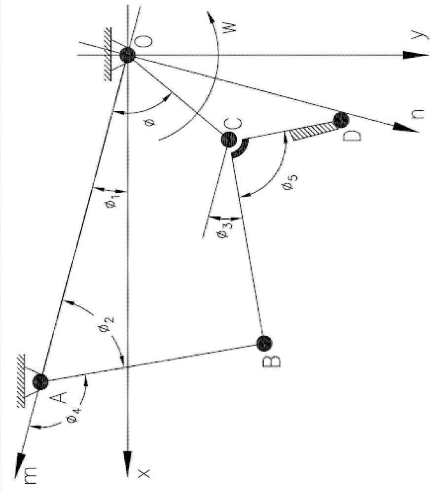
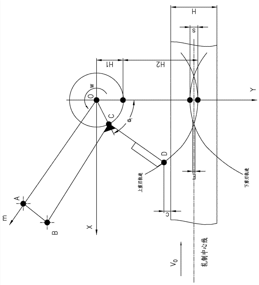
[0054] The original drawing of the upper cutting edge of the flying shears (the lower cutting edge is symmetrical to the rolling center line), as shown in figure 1 shown.

[0055] It is composed of crank OC, connecting rod AB and connecting rod BCD: wherein connecting rod BCD is welded by connecting rod BC and connecting rod CD, and the upper cutting edge is connected with connecting rod CD through a blade seat. The crank OC is driven by a motor to perform periodic rotary motion around its center of rotation O. It drives the connecting rod BCD and the upper cutting edge to move along the predetermined track through the hinge pair. One end B of the conn...


PUM


Abstract

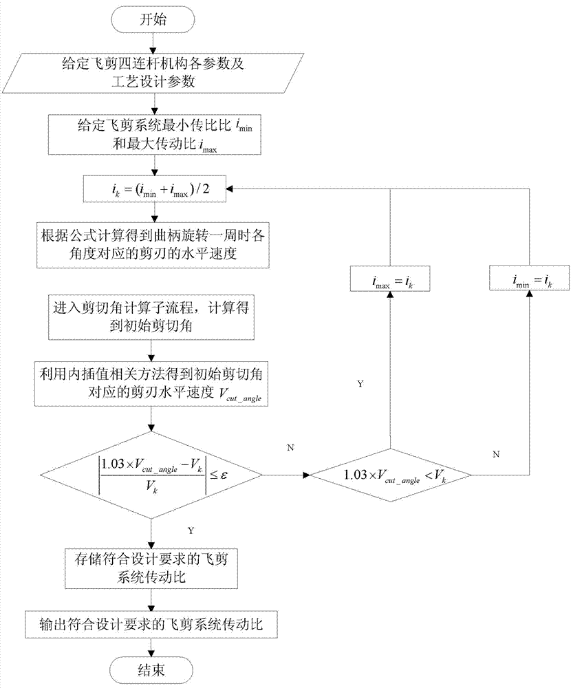
The invention discloses a hot-rolled steel section flying shear system speed reduction ratio control method. The method comprises the following steps: establishing a relevant parameter equation conforming to mechanical principles according to parameters; obtaining a space trajectory of a point D of an upper shear blade and a horizontal speed value of the shear blade corresponding to each angle when a crank rotates a circle; obtaining the initial shear angle of the shear blade according to the shearing process requirement of hot-rolled steel section flying shear; giving convergence margin tolerance and performing iterative judgment till meeting the iteration convergence condition of the equation, so as to obtain the system speed reduction ratio. The invention provides a method for determining the maximum value of the flying shear system speed reduction ratio suitable for given system parameters; and the method has good operability and routinization. The method departs from the three-dimensional parameterized software operating environment, reduces the labor intensity of project planners, and has good application prospects and practicability of engineering applications.

Description

technical field [0001] The invention relates to a control method of a hot-rolled section steel flying shear system, in particular to a method for controlling the reduction ratio of the hot-rolled section steel flying shear system. Background technique [0002] Flying shear is one of the important equipment in the steel rolling production line. It is arranged in front of the finishing rolling unit. It is used for cutting and breaking the head and tail of the rolled material during the hot rolling of section steel. It also has the function of segmentation to prepare for further rolling. , the quality of its working performance directly affects the production efficiency of the rolling line and the quality of the product cut. With the development of continuous rolling mills, flying shears have been used more and more widely. [0003] After the configuration of the crank-link type steel flying shear system and the design of each component are completed, the spatial trajectory of...

Claims


Application Information

Patent Timeline
Patent Type & Authority Patents(China)
IPC IPC(8): G06F17/30
Inventor 严国平许燚罗新华
Owner WISDRI ENG & RES INC LTD
Learn More