Sealing device capable of producing stealing identification mark

A technology of closing device and identification mark, which is applied in the field of anti-theft and anti-counterfeiting closing devices to achieve the effect of improving efficiency and solving manual assembly

Active Publication Date: 2012-12-26
余炳顺
View PDF2 Cites 0 Cited by
  • Summary
  • Abstract
  • Description
  • Claims
  • Application Information

AI Technical Summary

Problems solved by technology

Since the closing part is installed in the shell, it can be implanted manually, so it can solve the problem of manual assembly on site, which is conducive to improving work efficiency and showing new features

Method used


Image

  • Sealing device capable of producing stealing identification mark
  • Sealing device capable of producing stealing identification mark
  • Sealing device capable of producing stealing identification mark

Examples


Embodiment approach 1

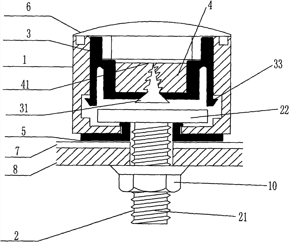
[0031] Embodiment 1: The closing part is clamped on the bottom of the clasp ring of the casing by a buckle mechanism, so that it is confined in the casing, but the closing part can move up and down freely in the casing.

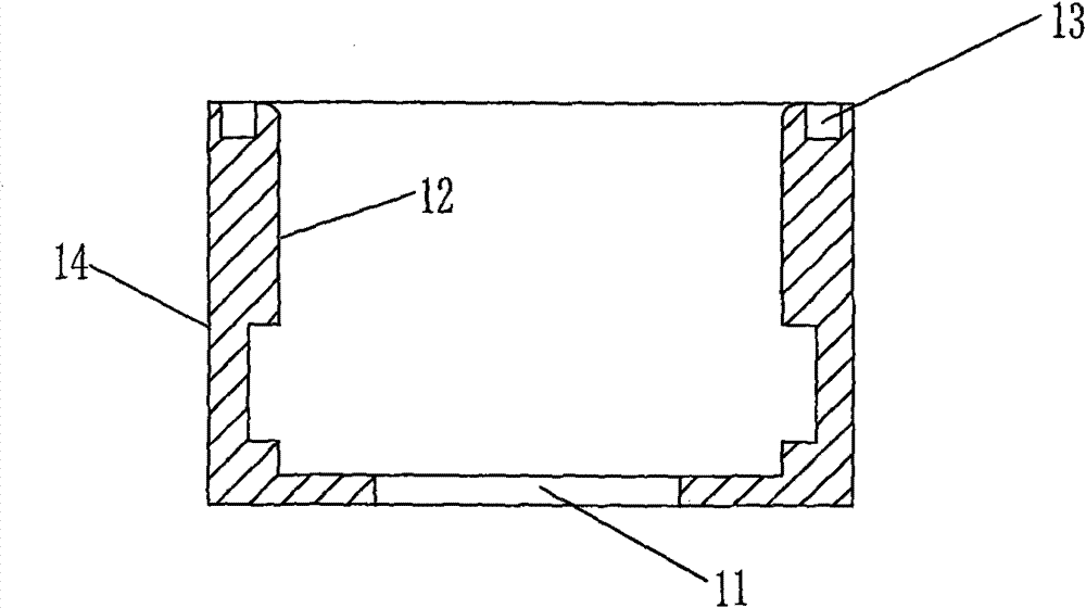
[0032] see Figure 1-Figure 5, the closing device for stealing identification includes a shell 1, a screw 2, a closing member 3, a lead 4, a chuck 5, and a transparent convex mirror 6. Among them: the shell 1 has a round hole 11 at the bottom, and a groove 13 is formed on the open end surface; the closing part 3 has a cavity 32, and the self-tapping screw 31 is installed on the closing part 3 and is located in the cavity 32; the chuck 5 is in the center A circular hole 51 is formed at the position, and a vertical cylinder 52 is formed by extending upward from the periphery of the circular hole 51. The cylinder 52 is formed with a card edge 53 extending outward along the horizontal direction at the port, and the diameter of the chuck 5 is smaller than the diam...

Embodiment approach 2

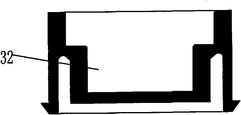
[0035] Implementation mode two: refer to Figure 6 The difference between the second embodiment and the first embodiment is the buckle mechanism. In this example, the buckle mechanism of the closure is formed by an oblate circle 32 embedded in the bottom of the closure, and the oblate circle 32 is buckled on the buckle At the bottom of 12, the closing member is constrained in the housing, but can rotate freely in the housing. For other details, see Embodiment 1.

Embodiment approach 3

[0036] Implementation Mode Three: Refer to Figure 7 The difference between the third embodiment and the first embodiment is the closing member. In this example, the closing member is formed by directly squeezing the lead 4 in the inner cavity of the shell 1, wherein the closing member is solid in the inner cavity. Tight, cannot turn. For other details, see Embodiment 1.


PUM


Abstract

The invention discloses a sealing device capable of preventing an unauthorized person from stealing a protected object in a counterfeiting way or by changing a connecting part to change the protected object without traces, which is applied to equipment required to be sealed by certain sectors or enterprises. The sealing device is characterized in that: the tail end of a bolt is extended out of a circular hole of a shell, and the head of the bolt remains in the shell; the circular hole is formed on a clamping disk; the periphery of the circular hole is upwards extended to form a vertical barrel which enters the circular hole of the shell from the outside; the clamping disk is closely attached to the outside of the bottom of the shell; the barrel is higher than the inner side of the bottom of the shell; a port of the barrel supports the inner top of the head of the bolt; an opening of the shell is sealed by a closing part; and whether the shell can freely rotate relative to the clamping disk or not is determined as the stealing identification mark. The device can function in preventing lawbreakers from stealing the protected objects in the changing or counterfeiting way.

Description

technical field [0001] The invention belongs to an anti-theft and anti-counterfeiting closing device, and relates to an anti-counterfeiting anti-counterfeiting of the closed parts of the device and identification of altered connecting parts, which are used to prevent protected objects such as motor vehicle license plates, containers, electric meter boxes, and water meters. Protection and identification devices that are opened or disassembled for transformation, resulting in theft or transformation of protected objects, applied to equipment that must be closed by specific departments or enterprises, such as license plates sealed by the motor license plate management department, sealed by the customs import and export yard Container etc., more specifically, is a kind of closing device that prevents unauthorized people from stealing by forging or changing the protected object without leaving a trace only by changing the connection part. Background technique [0002] Chinese uti...

Claims


Application Information

Patent Timeline
Patent Type & Authority Patents(China)
IPC IPC(8): G09F3/03B65D90/00
Inventor 余炳顺
Owner 余炳顺
Why Eureka
Try Eureka