
Rectifying system and method for X-ray intensifier

An X-ray and intensifier technology, applied in the field of image processing, can solve problems such as high computational complexity, decreased corner point accuracy, and inability to extract feature points, achieving accurate measurement and calculation and low distortion rate

Inactive Publication Date: 2013-01-09
SOUTH CHINA UNIV OF TECH
View PDF0 Cites 0 Cited by
  • Summary
  • Abstract
  • Description
  • Claims
  • Application Information

AI Technical Summary

Problems solved by technology

There are many methods of corner detection, such as the straight line detection method, which first performs edge extraction, straight line detection and fitting, and then obtains the precise coordinates of the corner point through the intersection of two straight lines. This method has high computational complexity and algorithm efficiency. Low, and when the image distortion is large, the accuracy of corner points extracted by this algorithm will drop sharply
Another example is to directly use the corner point extraction function to achieve this method. This method seems smart and simple, but when the distortion of the image is large, it will not be possible to extract all the feature points of the image, resulting in the failure of subsequent work. That is, this method is not general. , it is only in certain cases that a final X-ray intensifier correction can be achieved

Method used


Image

  • Rectifying system and method for X-ray intensifier
  • Rectifying system and method for X-ray intensifier
  • Rectifying system and method for X-ray intensifier

Examples


Embodiment 1

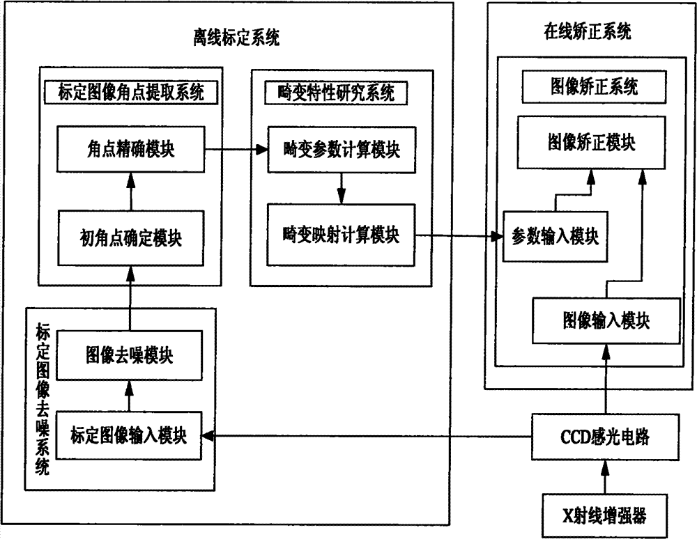
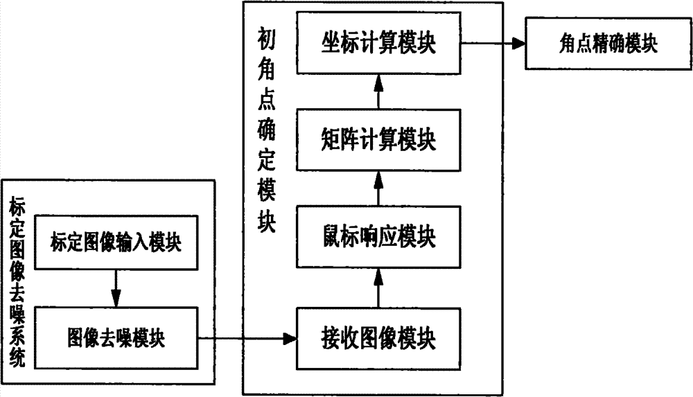
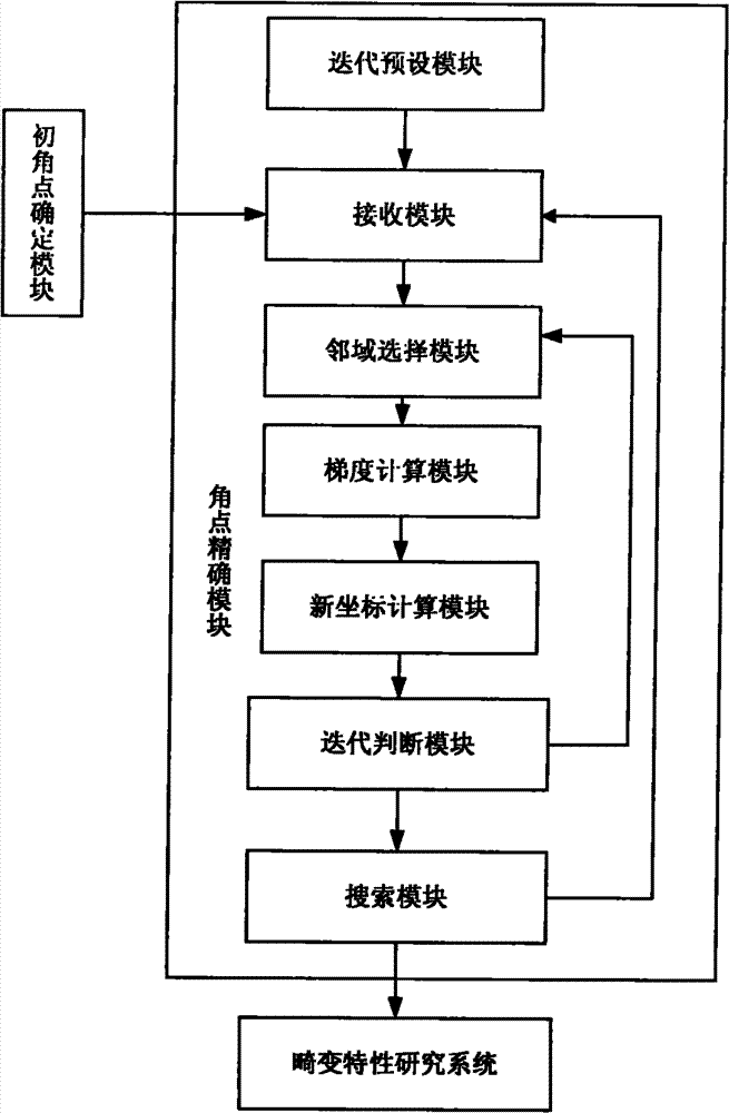
[0058] Such as figure 1 As shown, the X-ray intensifier correction system includes an X-ray source, an X-ray intensifier, a CCD photosensitive circuit and a control computer sequentially connected by an optical path. The control computer is provided with an offline calibration system and an online correction system. The offline calibration The system includes a calibration image denoising system, a calibration image corner extraction system and a distortion characteristic research system connected in sequence, the CCD photosensitive circuit is connected with the calibration image denoising system, the distortion characteristic research system is connected with an online correction system, and the The online correction system is connected to the CCD photosensitive circuit; a special calibration plate or a product under test is also placed between the X-ray source and the X-ray intensifier to connect with its optical path. When performing offline calibration through an offline c...

Embodiment 2

[0095] Other features of this embodiment are the same as embodiment 1 except the following features:

[0096] In the step (1-3-1), the several frames of calibration images are 25 frames of calibration images;

[0097] In the step (1-6), the number of sheets is twenty;

[0098] In the step (1-4-2), the number of corner points is ten.

[0099] The special calibration plate is a checkerboard calibration plate made of several metal sheets arranged at intervals on the base plate. The metal sheet is a high-density metal sheet; the substrate is a low-density non-metallic glass plate.

Embodiment 3

[0101] Other features of this embodiment are the same as embodiment 1 except the following features:

[0102] The special calibration plate is a checkerboard calibration plate made of several metal sheets arranged at intervals on the base plate. The metal sheet is a high-density metal sheet; the substrate is a low-density non-metallic wood board.


PUM


Abstract

The invention provides a rectifying system and method for an X-ray intensifier. The system comprises an X-ray source, the X-ray intensifier, a charge-coupled device (CCD) light-sensitive circuit and a control computer which are connected in sequence by light paths, wherein the control computer is provided with an offline calibrating system and an online rectifying system; the offline calibrating system comprises a calibrated image denoising system, a calibrated image corner point extracting system and a distortion characteristic studying system which are connected in sequence; the CCD light-sensitive circuit is connected with the calibrated image denoising system; the distortion characteristic studying system is connected with the online rectifying system; the online rectifying system is connected with the CCD light-sensitive circuit; and a special calibrating plate or product to be tested which is connected with the X-ray source and the X-ray intensifier by a light path is arranged between the X-ray source and the X-ray intensifier. The invention has the following beneficial effects: the calibrated images can be obtained by the offline calibrating system so as to obtain the distortion mapping parameters, the X-ray images of the product to be tested can be rectified in the online state and the X-ray images which are not distorted are output to be used in the subsequent procedures.

Description

technical field [0001] The invention belongs to the technical field of image processing, and in particular relates to an X-ray intensifier correction system and method for obtaining X-ray images from an X-ray intensifier by using a CCD photosensitive circuit and correcting the obtained X-ray images. Background technique [0002] At present, the X-ray image inspection system has been widely used in the product quality inspection process, that is, through the X-ray source irradiation, through the X-ray intensifier, the CCD photosensitive unit obtains the image of the product for product identification and quality inspection analysis. The X-ray intensifier mainly includes two components: a visible light conversion screen and an optical lens. Since the radius of the X-ray light source is not zero, X-ray imaging will produce a penumbra phenomenon, blurring the edge of the image, and the radial and tangential distortion introduced by the optical lens, resulting in distortion of th...

Claims


Application Information

Patent Timeline
Patent Type & Authority Patents(China)
IPC IPC(8): H01J31/50
Inventor 黄茜吴元徐道磊
Owner SOUTH CHINA UNIV OF TECH
Learn More