
Dyestripping method, dyestripping device and dyestripping equipment

A film device and drive device technology, applied in the direction of electrical components, semiconductor/solid-state device manufacturing, circuits, etc., can solve the problems of affecting the safety of wafers, affecting the quality of dicing films, and consuming tapes, so as to achieve a safe and reliable tearing process. The operation of tearing the film is simple and easy, and the effect of reducing the use of consumables

Active Publication Date: 2012-10-03
上海技美科技股份有限公司
View PDF4 Cites 0 Cited by
  • Summary
  • Abstract
  • Description
  • Claims
  • Application Information

AI Technical Summary

Problems solved by technology

[0007] 1. Tape is consumed every time the film is torn off
Adhesive tapes currently available in the market are more expensive, increasing the cost
Moreover, the tape cannot be recycled, and it will be discarded after one use, which not only costs high, but also produces garbage that is difficult to dispose of
[0008] 2. It is difficult to tear the film
Since the side of the thinning film that is not in contact with the wafer will be exposed to the air, anti-adhesive treatment is performed to prevent dust from sticking to it, and when the film is torn off, the adhesive tape and the thinning film are required to be stronger. These two requirements are mutually exclusive. Paradoxically, although the adhesion between the film and the wafer is not very strong, the adhesion between the tape and the film cannot be guaranteed to be successful every time because the back of the film is anti-adhesive. tear-off film
[0009] 3. Affect the security of the wafer
[0010] 4. Affect the quality of cutting film
For some types of thinning film, it needs to be heated to a certain temperature to be removed more reliably, which will cause the cutting film to be heated together, which will affect the quality of the cutting film and have a negative impact on the subsequent process
[0011] 5. Affect production efficiency
[0013] Although this method can change the dependence on the tape and partially reduce the cost of the tape, it does not fundamentally solve the problem of tape tearing
Firstly, the plastic film is still a consumable; secondly, the success rate is relatively low; thirdly, not every kind of thin film can be welded together with the plastic film; fourthly, the temperature, pressure and position of the heat welding need to be precisely controlled. It is difficult not to affect the dicing film and wafer

Method used


Image

  • Dyestripping method, dyestripping device and dyestripping equipment
  • Dyestripping method, dyestripping device and dyestripping equipment
  • Dyestripping method, dyestripping device and dyestripping equipment

Examples


Embodiment Construction

[0048] The present invention is described in detail below in conjunction with accompanying drawing:

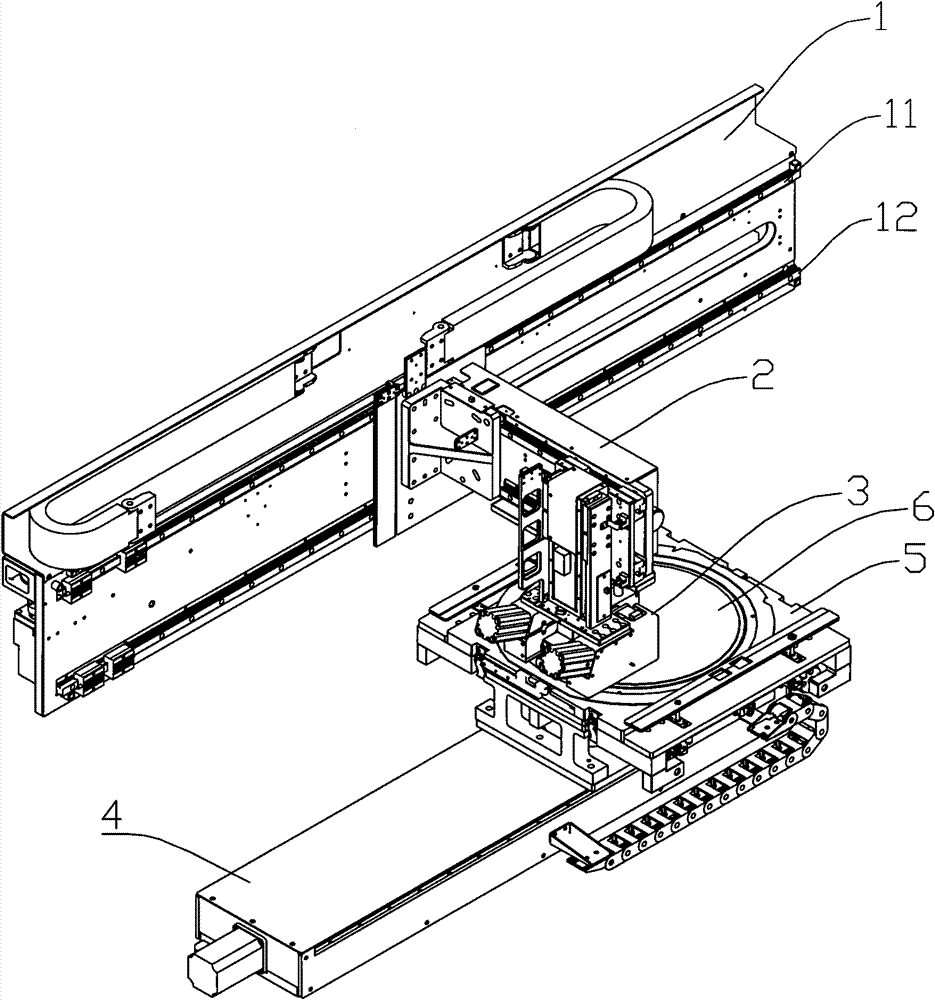
[0049] Such as figure 1As shown, the film tearing equipment includes a beam 1, and two parallel first guide rails (11, 12) are arranged on the beam 1. One end of the mechanical arm 2 cooperates with the two first guide rails (11, 12), and can move along the two first guide rails (11, 12). The movement of the mechanical arm 2 along the two first guide rails (11, 12) can be driven by known driving methods. The other end of mechanical arm 2 is equipped with film tearing device 3. A wafer carrying device 5 is provided below the film tearing device 3 for placing and fixing the wafer when tearing the film. A wafer carrier 5 is mounted on the base 4 . The wafer carrying device 5 can be fixedly installed on the base 4 ; it can also be movably installed on the base 4 , which can be realized by using a known installation method.

[0050] When tearing the film, the wafer 6 is placed...


PUM


Abstract

The invention discloses a dyestripping method. The dyestripping method is characterized in that film edges are separated from a substrate attached with the film edges; and a first fixture is used to clamp the film edges, and the first fixture is moved to gradually separate the film from the substrate attached with the film until the film and the substrate attached with the film are completely separated. The invention provides a novel dyestripping method which is as follows: a mechanical device is used for dyestripping in no need of using consumption materials such as tapes or films and the like, thereby reducing the use of consumable articles and effectively reducing the cost; and a dyestripping device can be recycled, thereby saving the cost of dyestripping. In the dyestripping device, dyestripping operation is simple and practicable, the success rate is high, the film on a wafer can be safely torn, thus the phenomenon that the tape can not be adhered with the film so that the film can not be torn is not occur; in the process of dyestripping, the operation of parts in the dyestripping device is easy to control, the precision is easy to handle, and the wafer can not be touched by the dyestripping device, thereby effectively avoiding the wafer is damaged and ensuring the safety of the wafer; and the dyestripping process is safe and reliable.

Description

technical field [0001] The invention relates to a film tearing method, a film tearing device and film tearing equipment. Background technique [0002] After the wafer production is completed, packaging and testing are required. Wafer production and packaging testing are often performed by different companies, therefore, need to be transported between different locations. In consideration of the safety of wafers during movement, the thickness of wafers manufactured by fabs is usually above 700um to prevent breakage during transfer. And as the size of the wafer increases, its thickness gradually increases. However, in the application of wafers, the development trend of chips is getting thinner and thinner. Therefore, before packaging and testing, the wafer needs to be thinned. [0003] Usually, the circuit side of the wafer, that is, the side that completes the chip function, is called the front side, and the other side is the back side. The back side of the wafer is main...

Claims


Application Information

Patent Timeline
Patent Type & Authority Patents(China)
IPC IPC(8): H01L21/00
Inventor 张明星刘永丰
Owner 上海技美科技股份有限公司
Learn More