Furniture drive

A technology for driving devices and furniture, applied in power control mechanisms, door/window accessories, buildings, etc., can solve the problems of prolonging assembly time and cost, and achieve the effect of small structural size

Active Publication Date: 2011-05-18
JULIUS BLUM GMBH
View PDF5 Cites 12 Cited by
  • Summary
  • Abstract
  • Description
  • Claims
  • Application Information

AI Technical Summary

Problems solved by technology

[0005] Therefore, in addition to the furniture drive, the switching unit must be additionally installed during assembly, which prolongs the assembly time and is relatively complex.

Method used


Image

  • Furniture drive
  • Furniture drive
  • Furniture drive

Examples


Embodiment Construction

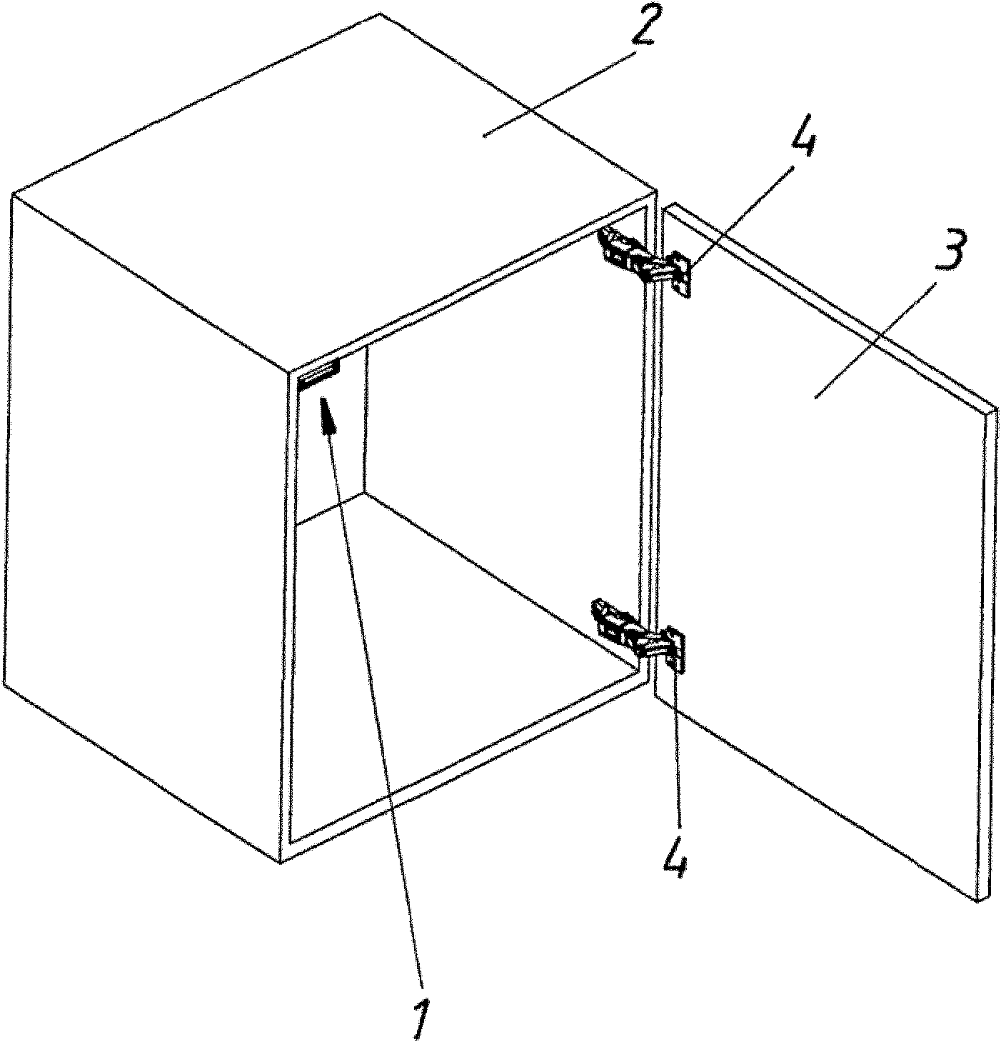
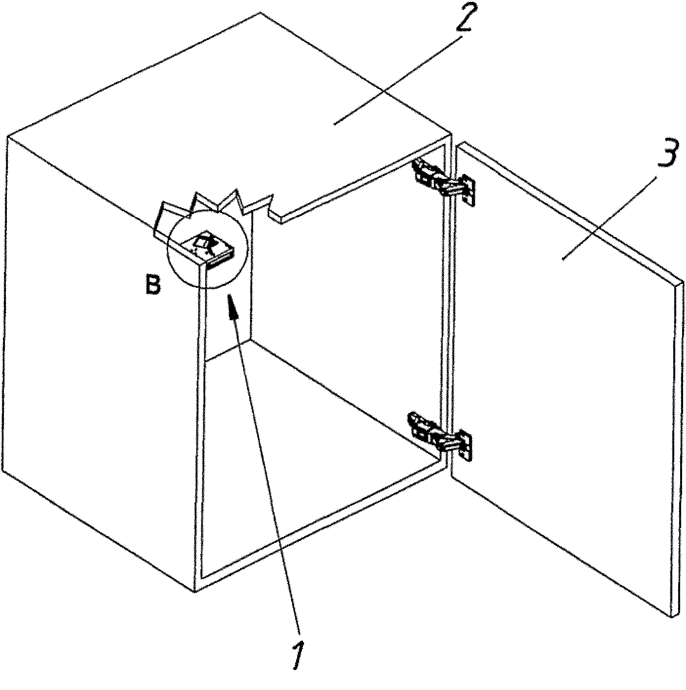
[0028] figure 1 A possible installation position of the furniture drive 1 according to the invention on the furniture body 2 remote from the hinges 4 is shown, about which hinges the movable furniture part as a furniture door can pivot.

[0029] Figure 2a with 2b can be seen in about figure 1 details.

[0030] The furniture drive 1 itself according to the invention is shown in more detail in FIGS. 3 to 5 .

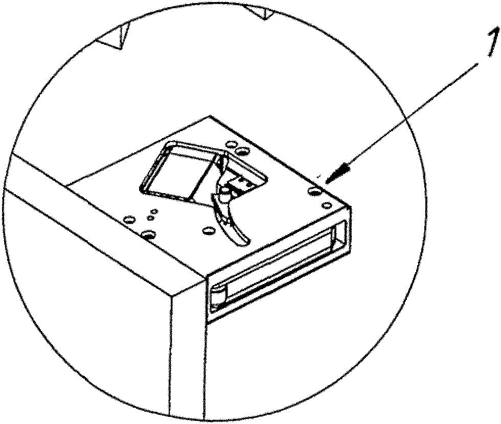
[0031] The upper side of the furniture drive 1 according to the invention is closed by a removable cover 8 . The drive unit 7 can be seen, which is designed as an electric motor in the exemplary embodiment.

[0032] The ejector 5 of the furniture drive 1 is designed here as an ejector lever, the free end of which is provided with a roller 6 . The roller 6 can also be omitted here.

[0033] can most easily be relied on Figures 5a to 5c The functional principle of the first embodiment of the furniture drive 1 according to the invention will be described.

[0034] ...


PUM


Abstract

The invention relates to a furniture drive (1) comprising an ejector (5) for ejecting a mobile furniture part from the closing position thereof, in or on a furniture body, and an energy accumulator (14) that can be charged by a drive unit (7) and discharged on the ejector (5) for ejecting the mobile furniture part. At least one electrical or electronic switching unit (15, 16) is provided for switching on and/or off the drive unit (7) and can be actuated by the ejector (5).

Description

technical field [0001] In a first aspect, the invention relates to a furniture drive comprising an ejector for ejecting a movable furniture part from its closed position in or on a furniture body and an energy store that can be charged by a drive unit, The energy store is provided with at least one electrical or electronic switching unit for switching on and / or switching off the drive unit in order to unload the lever-movable furniture part on the ejector. Background technique [0002] A similar furniture drive is known, for example, from WO 2004 / 101919 A1. [0003] Similar furniture drives allow moving furniture parts to be pushed out via an accumulator, but the accumulator does not have to be loaded by hand. The energy store can be charged via the drive unit independently of the moving furniture part. [0004] A disadvantage of similar furniture drives is the fact that, regardless of the installation situation of the furniture drive, an additional, external, ie, electric...

Claims


Application Information

Patent Timeline
Patent Type & Authority Applications(China)
IPC IPC(8): E05F15/12E05F1/10
CPCE05Y2400/326E05Y2900/20E05Y2201/22E05F15/127E05Y2201/426E05Y2201/434E05Y2400/324E05Y2600/458E05F1/105E05Y2201/424E05F15/63E05Y2201/624E05Y2400/854E05Y2400/856E05Y2800/11
Inventor 汗斯约尔格·布劳恩加特
Owner JULIUS BLUM GMBH
Why Eureka
Try Eureka