A wind turbine blade with angled girders

A technology of wind turbines and blades, which is applied to wind engines that are at right angles to the wind direction, wind engines that are consistent with the wind direction, and wind turbines, etc. It can solve beam fatigue failure, shell fatigue failure, and the design shape of the contour is no longer obtained Maintenance and other issues, to achieve the effect of increasing torsional characteristic frequency, low fatigue load, and improving aeroelastic stability

Inactive Publication Date: 2011-05-18
布拉德纳公司
View PDF2 Cites 16 Cited by
  • Summary
  • Abstract
  • Description
  • Claims
  • Application Information

AI Technical Summary

Problems solved by technology

[0009] Deformation of the beam at the connection between the beam and the shell can lead to fatigue failure of the beam and/or fatigue failure of the shell and/or fatigue failure at the connectio

Method used


Image

  • A wind turbine blade with angled girders
  • A wind turbine blade with angled girders
  • A wind turbine blade with angled girders

Examples


Embodiment Construction

[0071] The present invention will now be described more fully hereinafter with reference to the accompanying drawings, in which exemplary embodiments of the invention are shown. The drawings are schematic and simplified for the sake of clarity and only show details which are necessary for understanding the invention, while other details have been omitted. Throughout, the same reference numerals are used for the same or corresponding parts.

[0072] The invention can be embodied in different forms than those shown and should not be construed as limited to the embodiments set forth herein. Rather, these embodiments are provided so that this disclosure will be thorough and complete, and will fully convey the scope of the invention to those skilled in the art.

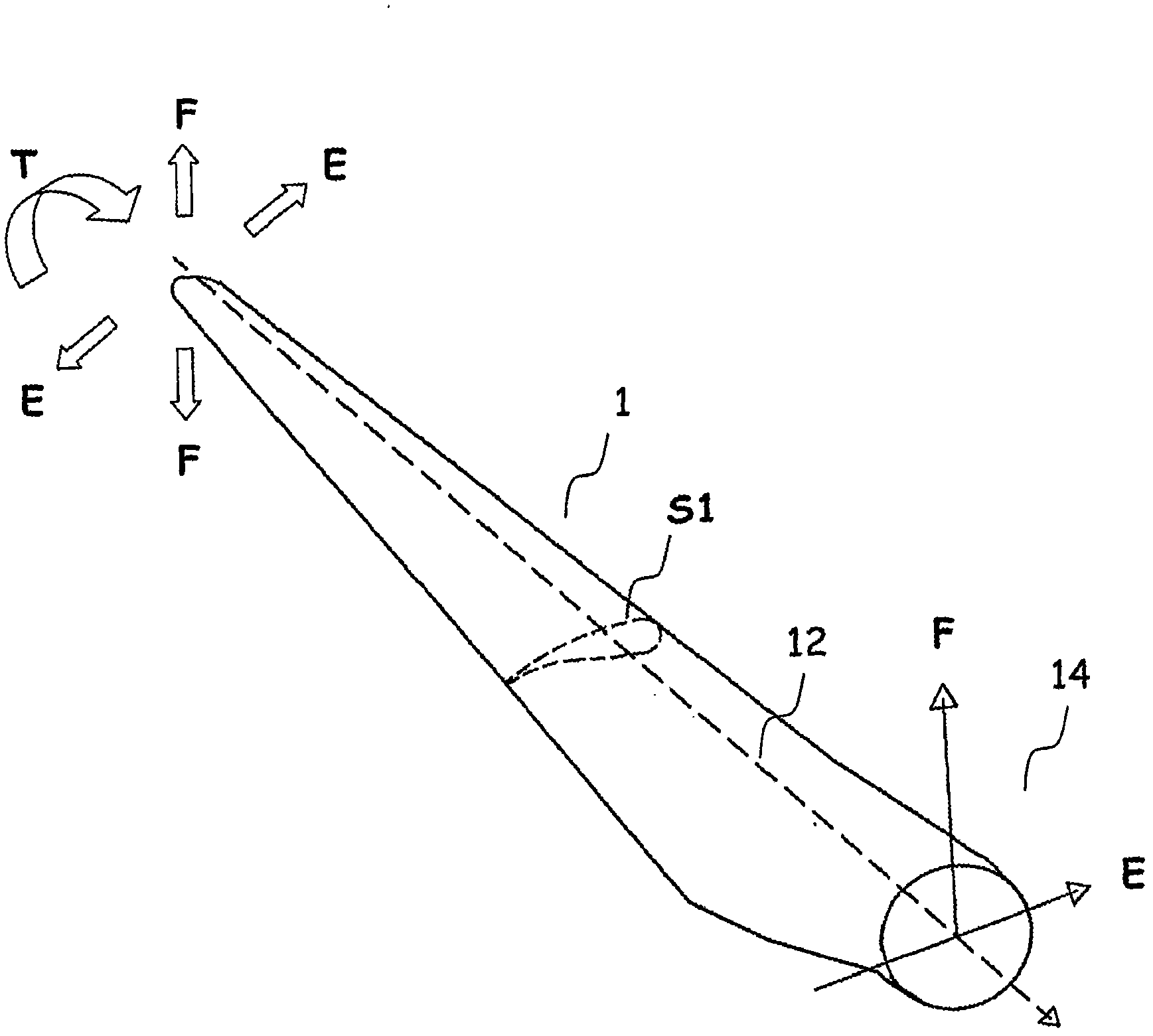
[0073] figure 1 A perspective view of a part of a wind turbine blade 1 is schematically shown together with arrows representing loads in the flapping direction F, the edgewise direction E and the torsional direction T, r...


PUM


Abstract

The present invention relates to a reinforced blade for a wind turbine, particularly to a blade having a new arrangement of two or more girders in the blade, wherein each of the girders is connected to the upper part and the lower part of the shell and forms an angle with another girder thereby strengthening the shell against transverse shear distortion.

Description

technical field [0001] The present invention relates to reinforced blades for wind turbines, in particular to a blade with a novel arrangement of one or more beams in order to prevent transverse shear deformation of the blade due to operational loads. Background technique [0002] Generally, a wind turbine blade has an aerodynamic shell and a beam, such as a beam or a spar. The beam can be a single beam, but usually two beams are used. The two beams together with the parts of the housing extending between the two beams form a so-called box profile. The bottom and top of the box profile are often called caps. Some types of blades are designed with spars in the form of box profiles, which are fabricated separately and bonded between prefabricated surface shells. Aerodynamic shells are generally made of fiber reinforced plastic, fiberglass, and / or laminates of other materials. Typically, the aerodynamic shell is made of two shell parts which are assembled to form the shell....

Claims


Application Information

Patent Timeline
IPC IPC(8): F03D1/06F03D3/06
CPCF03D1/0675F05C2253/04Y02E10/72F05B2280/6003F03D3/062F05B2240/301F05B2210/16Y02E10/721Y02E10/74Y10T29/49339
Inventor 芬德·莫霍尔特·詹森
Owner 布拉德纳公司
Why Eureka
Try Eureka