
Skeletal III-type malocclusion appliance

An orthodontic device and malocclusion technology, applied in the field of medical appliances, can solve problems such as excessive opening and closing of front teeth, unsightly appearance, uncontrollable thickness of permanent magnets, etc., and achieve the effect of easy promotion

Inactive Publication Date: 2011-05-25
王丽艳
View PDF4 Cites 12 Cited by
  • Summary
  • Abstract
  • Description
  • Claims
  • Application Information

AI Technical Summary

Problems solved by technology

Since the dental tray can only be made manually by the doctor, the permanent magnet also needs to be installed by the doctor on site, so the production is difficult and time-consuming, and the metal wire is exposed to the front teeth during use, which is not very beautiful
Moreover, the thickness of the permanent magnet placed on the occlusal surface of the teeth cannot be controlled, resulting in excessive opening and closing of the anterior teeth, resulting in unclear pronunciation. Many experts have also questioned whether it will cause problems with the temporomandibular joint, so it has been difficult to promote

Method used


Image

  • Skeletal III-type malocclusion appliance
  • Skeletal III-type malocclusion appliance
  • Skeletal III-type malocclusion appliance

Examples


Embodiment 1

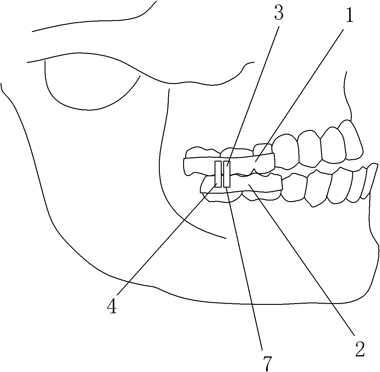
[0034] Such as figure 1 As shown, the present invention includes an upper conjoined crown 1 set on the upper molars, and a lower conjoined crown 2 placed on the lower molars. A first permanent magnet 3 is fixed on the buccal side of the upper conjoined crown 1, and a first permanent magnet 3 is fixed on the buccal side of the lower conjoined crown 2. The buccal side is fixed with a second permanent magnet 4, in the state where the upper and lower rows of teeth are closed, that is, in the figure 1 In the state shown, the first permanent magnet 3 on the upper conjoined crown 1 is located in front of the second permanent magnet 4 on the lower conjoined crown 2 and has the same poles facing each other. The mutual repulsion between the first permanent magnet 3 and the second permanent magnet 4 is preferably not less than 500 grams, so as to ensure that the jaw bone changes. The dimensions of the first permanent magnet 3 and the second permanent magnet 4 are 3×5×5 mm. The first pe...

Embodiment 2

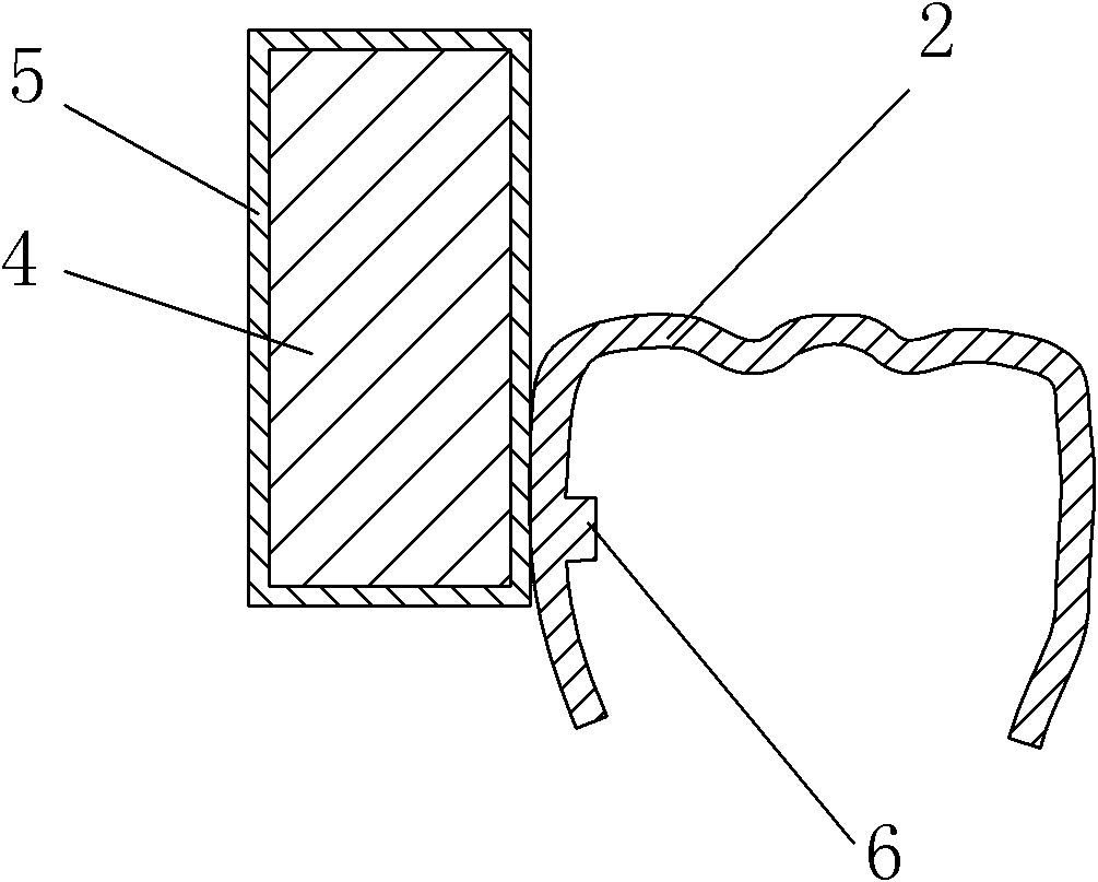
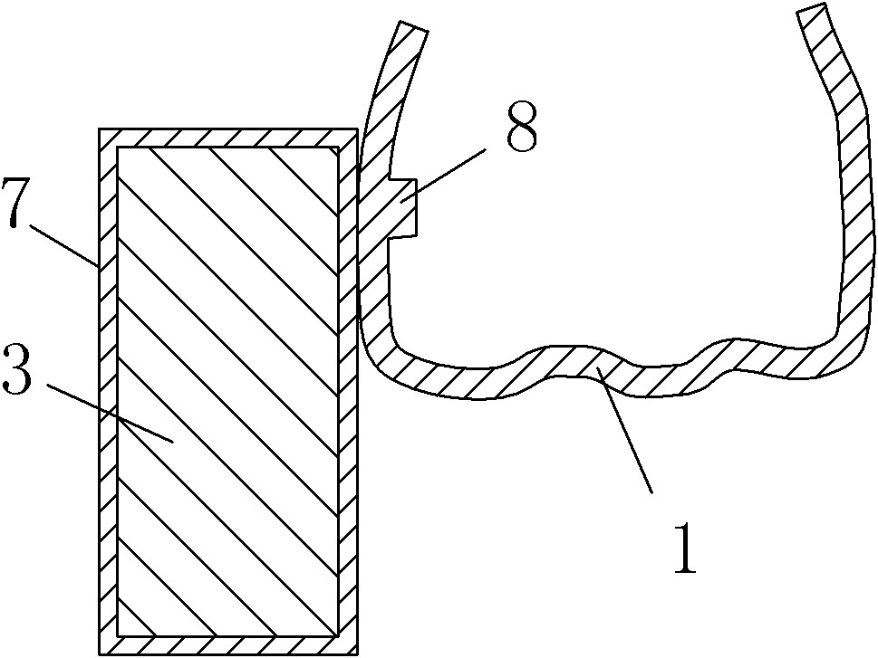
[0050] Embodiment two is the further improvement of embodiment one, as figure 2 As shown, the lower conjoined crown 2 is integrally formed with a second protrusion 6 between the teeth; as image 3 As shown, the upper conjoined crown 1 is integrally formed with a first protrusion 8 abutting between the teeth. Adopting the above-mentioned structure can make the fixation between the upper conjoined crown 1 and the lower conjoined crown 2 and the molars more firm.


PUM


Abstract

The invention belongs to the technical field of medical appliances, in particular to a skeletal III-type malocclusion appliance which is used for treating skeletal III-type malocclusion. The skeletal III-type malocclusion appliance comprises an upper conjoined crown sleeved on upper molars and a lower conjoined crown sleeved on lower molars; a first permanent magnet and a second permanent magnet are respectively fixed to the buccal sides of the upper conjoined crown and the lower conjoined crown; in the state that the upper row of teeth and the lower row of the teeth are closed, the first permanent magnet of the upper conjoined crown is positioned in front of the second permanent magnet of the lower conjoined crown and the like polarities are opposite to each other; and due to the thickness of an occlusal surface of the upper conjoined crown and the lower conjoined crown, the incisal edge of upper incisor teeth is higher than the incisal edge of lower incisor teeth. Compared with conventional appliance, the skeletal III-type malocclusion appliance does not influence work, study and sleep, is not easy to expose when in use, is easy to be accepted by patients, and is easier to popularize.

Description

technical field [0001] The invention belongs to the technical field of medical appliances, in particular to a skeletal class III malocclusion appliance for treating skeletal class III malocclusion. [0002] In particular, "wrong jaw" should be "wrong (occlusal)" in the field of dentistry, and (occlusal) is a word composed of teeth and joints, which is a special word in the field of dentistry and cannot be typed by a computer, so the present invention is written as "" wrong jaw". Background technique [0003] The safest way to treat skeletal Class III malocclusion (commonly known as "ground cover") is to allow patients to wear orthotics to correct bone deformities during or before growth and development. At present, known such appliances are mainly divided into two types, one is worn on the patient's face, and the other is worn on the patient's teeth. [0004] The former type of appliance has the defects of complex structure and uncomfortable wearing. This appliance is a m...

Claims


Application Information

Patent Timeline
IPC IPC(8): A61C7/08
CPCA61C7/006
Inventor 王丽艳
Owner 王丽艳
Learn More