Image recording simulation in a coordinate measuring machine

a technology of image recording and coordinate measuring machine, which is applied in the field of image recording simulation in a coordinate measuring machine, can solve the problems of just usable measurement and a high degree of experience, and achieve the effect of improving the rendering step and improving the quality of calculations

Active Publication Date: 2018-06-05
CARL ZEISS IND MESSTECHN GMBH
View PDF9 Cites 0 Cited by
  • Summary
  • Abstract
  • Description
  • Claims
  • Application Information

AI Technical Summary

Benefits of technology

[0014]This makes it possible to perform a complete simulation of the image recording of an object or object region using the methods of rendering on the basis of the object properties known in measurement technology from CAD data. This measurement may be supported by one or more real measurements, as will be explained below.
[0023]This enables a user to “scroll” through the image stack and observe effects of the variations. By way of example, with a specific predefined virtual illumination it is then possible to scroll along the optical axis of the lens and to observe the detected partial region of the measurement object or the measurement object as a whole in different planes. Moreover, an, in particular automatic, assessment of the recordings with regard to usability for a measurement is made possible in this way. The user may thus not only select the desired parameter composition, for example the position of the focal plane in the real measurement, but possibly also modify, or cause to be automatically modified, the settings for the virtual illumination or the size of the detected partial region until the quality of the simulated virtual image appears to be sufficient. With regard to the quality of the image recording, it thus becomes possible, in particular, to identify different convergence ranges of an optimization of the quality of the image recording that are possibly present. The settings underlying the calculation may then be accepted in the real coordinate measuring machine and the real measurement may be carried out on this basis. This therefore makes it possible to avoid a time-consuming setting method dependent on the user's experience and ability on the real coordinate measuring machine.
[0028]The method in accordance with the second aspect of the invention thus involves firstly providing a first, a second and a third data set, wherein the step of providing corresponds to that of the method in accordance with the first aspect. Here, too, the fourth data set described above may additionally be provided. A process of simulating an image recording by rendering is then likewise effected. In this case, at least one virtual image imaged on the optical sensor is calculated. The user may observe said at least one virtual image or subject it to an automated evaluation and an illumination of the measurement object may be set or varied on the basis thereof. In this way it becomes possible, without having to perform settings on the real coordinate measuring machine, to be able to perform a setting of an illumination on the coordinate measuring machine more time-efficiently and without required experience in handling coordinate measuring machines.
[0040]In this way, the user may then apply the settings that are output to the real coordinate measuring machine and thus directly carry out the measurement with a best image recording setting.
[0050]In this way it likewise becomes possible to improve the quality of the calculations during the step of rendering. As already described above, the real image may be fitted into the image stack on the basis of a correlation with the virtual images of the image stack. The virtual image to which there is the best correspondence in the context of the correlation is then compared with the actual image. Deviations between the real image and the virtual image may be ascertained in this way and used for example for improving the step of rendering if it is performed once again. Furthermore, it becomes possible also to apply the deviations to the virtual images for the purpose of improvement.

Problems solved by technology

However, the setting of the illumination in practice requires a high degree of experience on the part of the operating personnel of the coordinate measuring machine or else is very time-consuming, since possibly one or more measurement passes with poor illumination are initially carried out in order to iteratively approximate to the best illumination.
Consequently, the operator thus has to carry out a plurality of attempts before arriving at an appropriate illumination which then yields only just usable measurement results.

Method used


Image

  • Image recording simulation in a coordinate measuring machine
  • Image recording simulation in a coordinate measuring machine
  • Image recording simulation in a coordinate measuring machine

Examples


first embodiment

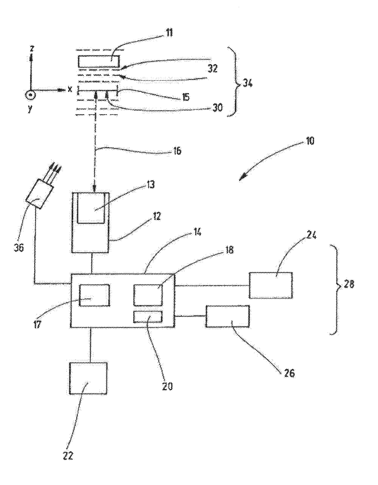
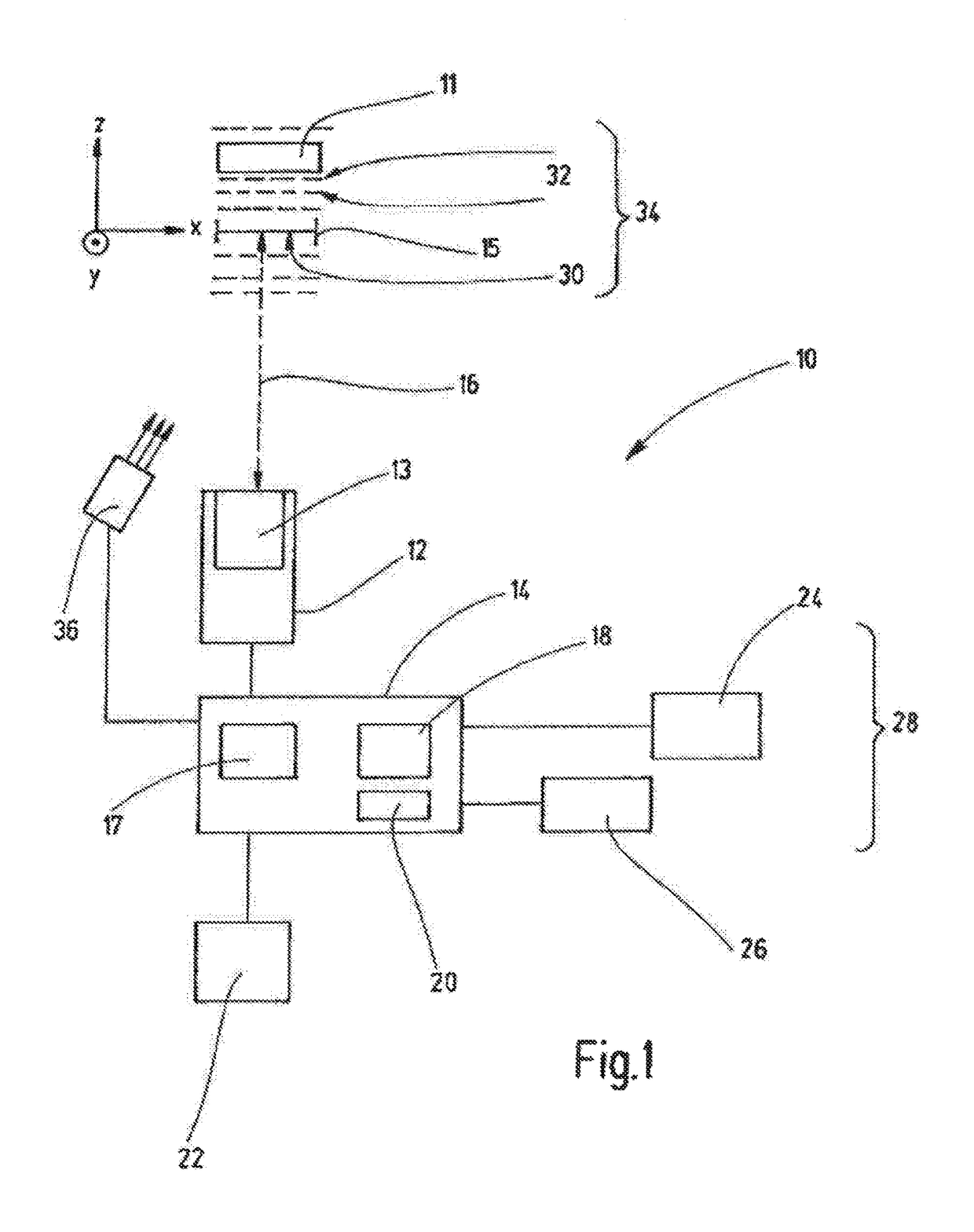
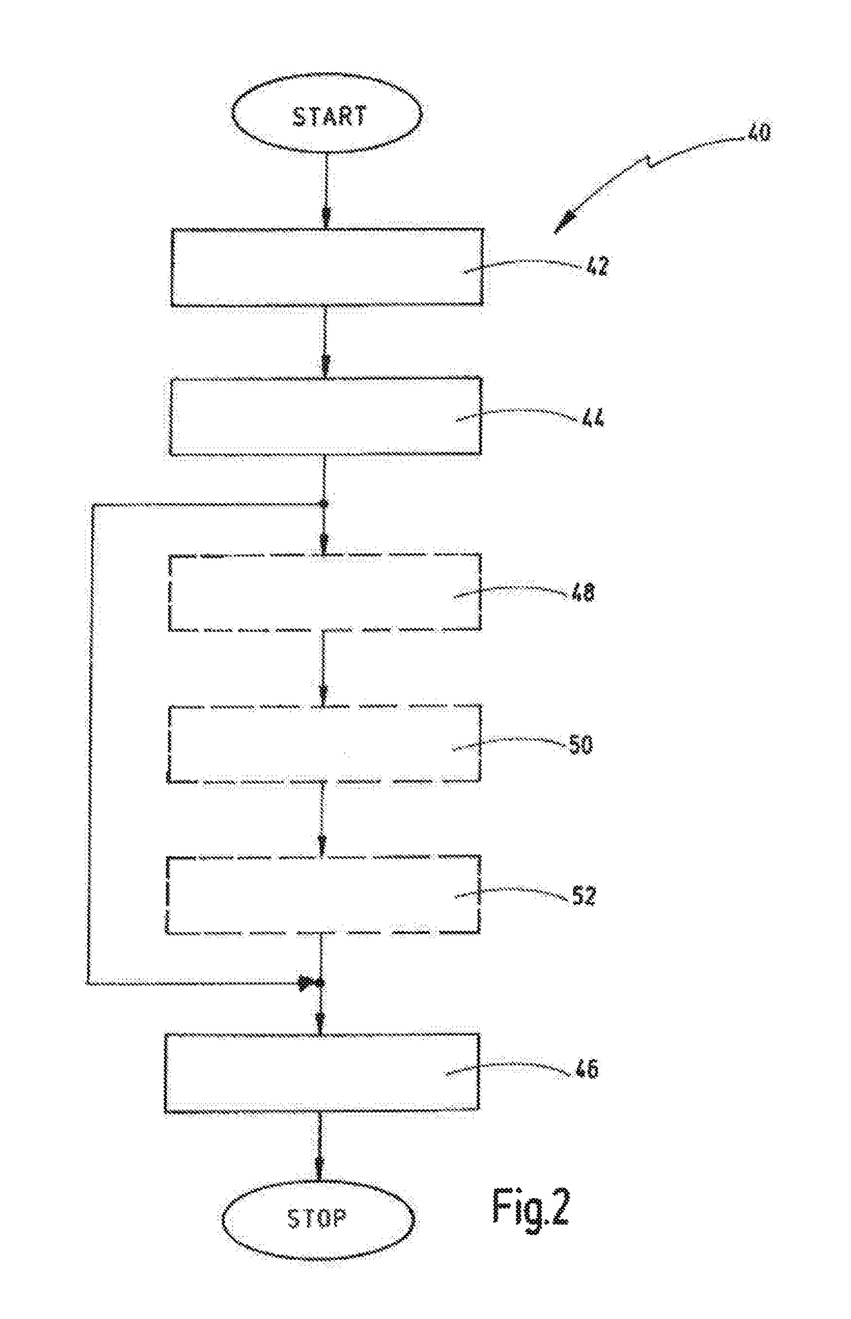
[0089]FIG. 2 shows a method for optimizing an illumination of a measurement object in a coordinate measuring machine. The method is identified generally by the reference sign 40.

[0090]After the start, there is carried out firstly a step 42 of providing a first data set representing a model of the measurement object 11, a second data set representing a model of an illumination 36 of the measurement object 11, and a third data set representing a model of an optics 13 of the optical sensor 12.

[0091]Afterward, there is carried out a step of simulating 44 at least one virtual image of the measurement object 11 imaged onto the optical sensor 12 by rendering on the basis of the first data set, the second data set and the third data set. Afterward, in one configuration, the step of setting 46 the illumination of the measurement object 11 on the basis of the at least one simulated virtual image of the measurement object 11 may then be carried out directly.

[0092]In this way, the setting metho...

second embodiment

[0096]FIG. 3 shows one possible second embodiment of the method 40.

[0097]Firstly, identical steps 42 and 44 are carried out. Afterward, a step 48 involves ascertaining the quality of the illumination of a measurement object by determining a value of a parameter representing the quality from at least one of the at least one rendered virtual image.

[0098]A comparison of said parameter with a limit value follows in a step 54. If the interrogation is negative, the second data set, i.e. the illumination setting, is varied and the step of simulating 44 and ascertaining 48 is repeated. If the interrogation is positive, afterward step 46 is performed with the settings and the ascertained setting of the illumination of the measurement object on the real coordinate measuring machine 10 is carried out.

[0099]FIG. 4 shows one embodiment of a method 60 for simulating an imaging on an optical sensor of a coordinate measuring machine 10 for inspecting a measurement object 11.

[0100]Firstly there is c...

fourth embodiment

[0110]However, FIG. 7 also shows the method 60.

[0111]Firstly, in a step 84 by means of a measurement, for example by means of a wavefront aberrometer, the aberration of the lens or of the optics of the coordinate measuring machine is determined and stored for example in the form of a Zernike polynomial.

[0112]The step of providing 62 can thus be effected as described above. Afterward, at least one real image may be recorded in a step 86, in order to support step 64 of rendering. A step of rendering is to be carried out for example using the at least one real image as a starting value and a phase retrieval.

[0113]Subsequently, in a step 88, the at least one real image is then fitted into the image stack rendered step 64 and the aberrations are subtracted from the corresponding virtual images. Deviations remaining between the real image and the corresponding virtual image may likewise be ascertained and then taken into account when determining the image having a best image recording set...


PUM


Abstract

The present invention relates to a method for simulating an image recording by an optical sensor of a coordinate measuring machine for inspecting a measurement object, comprising the following steps: providing a first data set representing a model of the measurement object, a second data set representing a model of an illumination of the measurement object, and a third data set representing a model of an optics of the optical sensor, and rendering an image stack on the basis of the first data set, the second data set and the third data set, wherein the image stack has a plurality of virtual images of at least one partial region of the measurement object, wherein each virtual image is rendered at least with a different second and / or different third data set. Furthermore, the present invention relates to a method for optimizing an image recording by a coordinate measuring machine.

Description

CROSS-REFERENCE TO RELATED APPLICATIONS[0001]This is a Continuation application of International patent application PCT / EP2014 / 051050, filed Jan. 20, 2014, the contents of which are incorporated herein by reference.BACKGROUND OF THE INVENTION[0002]The present invention relates to a method for simulating an imaging onto an optical sensor of a coordinate measuring machine for inspecting a measurement object. Furthermore, the present invention relates to a method for optimizing an illumination of a measurement object in a coordinate measuring machine with an optical sensor.[0003]Coordinate measuring machines as such are generally known. They are used in industrial applications for example for quality assurance or measuring components in retro-fit processes or other applications. By means of the coordinate measuring machines, geometries and dimensions of components for the purpose thereof are measured with high accuracy. Various measuring methods differentiated, in principle, into so-ca...

Claims


Application Information

Patent Timeline
Patent Type & Authority Patents(United States)
IPC IPC(8): H04N5/228G06T15/00H04N5/232H04N5/235G06T7/32G01B11/24G01B11/00G01B11/25G06T7/00
CPCG01B11/005G01B11/24G01B11/25G06T7/0002G06T7/32H04N5/2351H04N5/23212G06T15/00G06T2207/30168G06T7/0026H04N23/67H04N23/71
Inventor ENGEL, THOMASHAVERKAMP, NILSWICK, MICHAELFRASCH, HANS-JOACHIM
Owner CARL ZEISS IND MESSTECHN GMBH
Why Eureka
Try Eureka