Lower press plate used by flat bed guide rail of machine tool

A technology of flat bed and pressure plate, which is applied in the direction of metal processing machinery parts, large fixed members, metal processing equipment, etc., can solve the problems of increased use cost, time-consuming and laborious, and reduced shock resistance of moving parts, so as to prolong the service life and reduce the use of cost effect

Inactive Publication Date: 2011-05-25
CHONGQING HONGGANG CNC MACHINE TOOL
View PDF3 Cites 2 Cited by
  • Summary
  • Abstract
  • Description
  • Claims
  • Application Information

AI Technical Summary

Problems solved by technology

Because of the sliding friction between the platen surface 101 and the lower surface of the bed body 201, when the machine tool is working, no matter what materials are used for the platen surface 101 and the lower surface of the bed body 201, it will be worn away, and there will be a gap between the worn platen surface 101 and the lower surface of the bed body 201. If there is a gap, the gap will affect the accuracy of the machine tool, that is, the rigidity will decrease, which will reduce the shock resistance of the moving parts on the guide rail, and cause shutdown in severe cases
To restore the accuracy of the machine tool, it is necessary to re-adjust it or scrape the pressure plate. Whether it is debugging the machine tool or scraping the pressure plate, professional and technical workers in this field are needed. When looking for professional workers, it will not only affect production efficiency, but also increase The cost of use is time-consuming and labor-intensive; moreover, even for professional workers, it is difficult to debug to the accuracy of the factory. This problem is difficult to solve in the machining equipment industry.
[0003] In summary, using the dead platen used in the flat bed of the machine tool in the prior art has high cost of use, low production efficiency and inability to debug the machine tool conveniently and quickly.

Method used


Image

  • Lower press plate used by flat bed guide rail of machine tool
  • Lower press plate used by flat bed guide rail of machine tool
  • Lower press plate used by flat bed guide rail of machine tool

Examples


Embodiment Construction

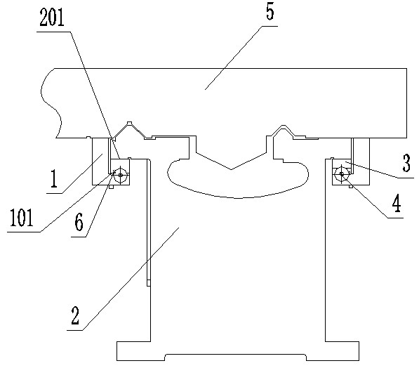
[0012] Below in conjunction with accompanying drawing and embodiment the present invention will be further described:

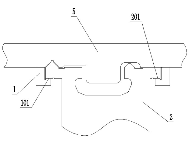
[0013] See attached figure 2 , the lower platen for the guide rail of the flat bed of the machine tool in the figure includes a platen seat 1 and a platen surface 101 arranged on the platen seat 1 to cooperate with the lower surface of the machine bed, wherein: the platen surface 101 is provided with inclined inserts 3, inclined The inlay 3 is connected to the platen seat 1 through the double-headed adjusting bolt 4 passing through the platen seat 1 . During use, the bevel insert 3 is wedge-shaped, the big end is outside, and the small end is installed inside. By adjusting the double-ended adjusting bolt 4, the worn bevel insert 3 is directly adjusted to the Z of the machine tool, and adjusted to the factory precision of the machine tool. until.

[0014] The oblique insert described in this embodiment is provided with a forced lubrication hole 6 , and the ...


PUM


Abstract

The invention relates to a lower press plate used by a machine tool bed in a mechanical manufacturing device, and in particular relates to a lower press plate used by a flat bed guide rail of a machine tool, comprising a press plate seat and a press plate surface which is arranged on the press plate seat and matched with a downslide surface of the machine tool bed, wherein an oblique cam is arranged on the press plate surface, and the oblique cam is connected to the press plate seat by stud adjusting bolts passing through the press plate seat. The lower press plate provided by the invention has the following advantages: the service life is prolonged, the disabled machine tool can be adjusted to the delivery precision simply and rapidly, and the cost is reduced.

Description

technical field [0001] The invention relates to a lower pressing plate for a machine tool bed in mechanical manufacturing equipment, in particular to a lower pressing plate for a machine tool flat bed guide rail which improves production efficiency, reduces use costs and can arbitrarily restore the factory precision of the machine tool. Background technique [0002] In recent years, machine tools have continued to develop in the machining industry. In order to ensure the accuracy of machine parts processed by machine tools, people have continuously improved the structure of the machine tool itself and the structure of its components to improve the machining accuracy. As we all know, the accuracy of machined parts is mainly determined by the stability of the machine tool, and the stability of the machine tool will decrease with the use of time. The saddle, the moving part of the machine tool, is connected to the bed through the lower pressing plate, and moves along the guide ...

Claims


Application Information

Patent Timeline
Patent Type & Authority Applications(China)
IPC IPC(8): B23Q1/01
Inventor 汪传宏
Owner CHONGQING HONGGANG CNC MACHINE TOOL
Why Eureka
Try Eureka