Free mobile gate seat tower crane

A technology of tower cranes and portal towers, which is applied to cranes and other directions, can solve the problems of adaptability, insufficient efficiency, high work efficiency, and difficulty in changing the height of the machine body, etc.

Active Publication Date: 2011-05-25
SINOHYDRO BUREAU 7 CO LTD +1
View PDF5 Cites 10 Cited by
  • Summary
  • Abstract
  • Description
  • Claims
  • Application Information

AI Technical Summary

Problems solved by technology

Wheel-type mobile cranes, such as car-chassis car cranes and tire-based cranes with special chassis, are flexible and convenient to move, and are especially suitable for lifting and transporting in mobile working conditions. However, the crane chassis is low and occupies a large space. The site application is limited; the gantry crane is supported by the lower door frame, which can improve the passage conditions of the lower passage of the arch body, and is especially suitable for hoisting operations in narrow and long workplaces. However, the crane uses wheel-rail travel and the height of the body is not easy to change, so there are corresponding work restrictions. ;Tower crane (self-elevating) tower bearing, flexible height change, good adaptability, trolley traction and variable amplitude, high work efficiency, but there are also work restrictions such as no traffic conditions in the lower part and wheel-rail walking
[0003] In road and bridge projects such as highway, railway pavement, bridge deck construction, building construction in narrow and long spaces or passages, cargo yard hoisting operations, etc., the above-mentioned products have insufficient adaptability and efficiency.
At present, there is no tire walking, door seat support, self-elevating tower lifting equipment that can adapt to road running, provide lower passage conditions, the height of the whole machine is flexible and changeable, and has high work efficiency.

Method used


Image

  • Free mobile gate seat tower crane
  • Free mobile gate seat tower crane
  • Free mobile gate seat tower crane

Examples


Embodiment Construction

[0031] The present invention is further described below in conjunction with embodiment. The examples are used to illustrate the present invention, and do not limit the scope of protection of the present invention in any way.

[0032] combine Figure 1 to Figure 9 .

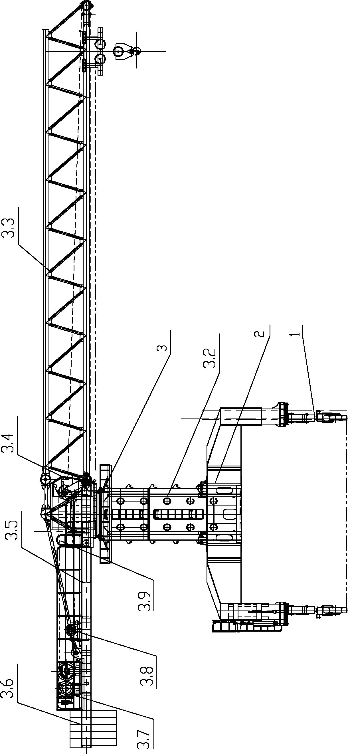
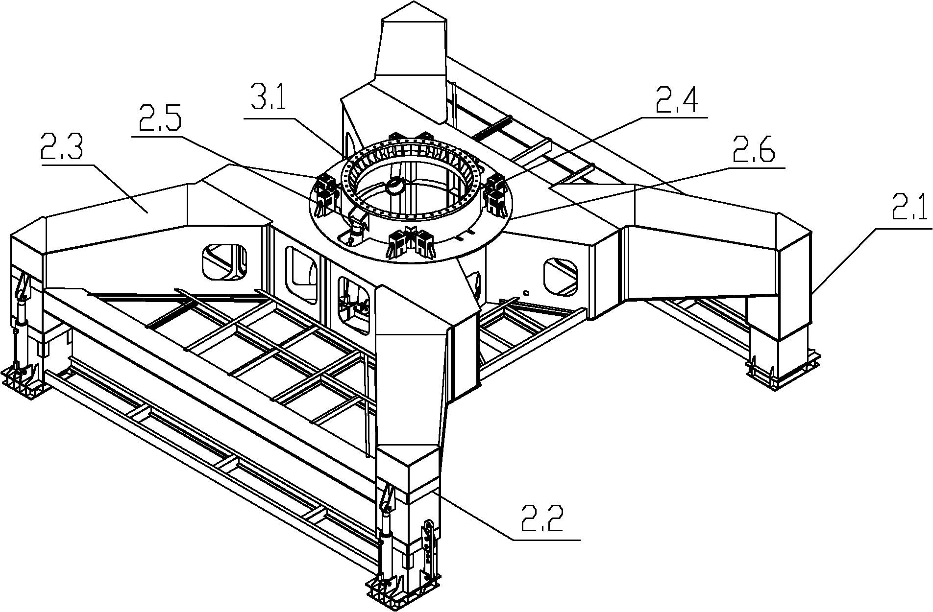
[0033] figure 1 It is a schematic diagram of the overall structure of a free-moving portal tower crane, as shown in the figure, including a traveling mechanism 1, a tower crane mechanism 3, and a portal supporting device 2 connecting the traveling mechanism 1 and supporting the tower crane mechanism 3; the traveling mechanism 1 is the trackless tire traveling mechanism, the tower crane mechanism 3 is installed on the door seat supporting device 2, and the door seat supporting device 2 is installed on the four groups of traveling mechanisms 1 to realize movement.

[0034] The tower crane mechanism 3 includes a foundation tower column 3.1 connected to the tower crane support platform 2.6, a tower crane mechanism ...


PUM


Abstract

The invention discloses a free mobile gate seat tower crane, comprising walking mechanisms and a tower hoisting mechanism, wherein the walking mechanisms are trackless tire walking mechanisms; and the tower hoisting mechanism is arranged on a gate seat supporting apparatus which is arranged on four groups of walking mechanisms to implement the movement. The trackless tire walking mechanisms are adapted to various mobile working environments and have the walking mobility on various roads; lateral rubber guide pulleys can guide and limit the wheels to smoothly pass along a vertical guide wall so as to improve the walking safety; the gate seat supporting apparatus can make the vehicles under the crane pass through freely; height-varying supporting legs make the crane adapt to the roads with higher grades on two sides; a span regulating apparatus can regulate the span between the wheels to adapt to different road widths, and a supporting platform is connected with a foundation tower column and a standard tower column to realize the assembly and operation in low position and the operation and disassembly in high position. The invention is a hoisting apparatus which is capable of beingadapted to a large operation range and complex working conditions and can move freely.

Description

technical field [0001] The invention belongs to the field of hoisting machinery, in particular to the field of movable hoisting machinery, in particular to a tower crane with a freely movable portal. Background technique [0002] Rubber-tyred mobile cranes, gantry cranes, and tower cranes, as mature lifting equipment products, have been widely used in different occasions of engineering construction and hoisting operations due to their respective conditions of use and working characteristics. Wheel-type mobile cranes, such as car-chassis car cranes and tire-based cranes with special chassis, are flexible and convenient to move, and are especially suitable for lifting and transporting in mobile working conditions. However, the crane chassis is low and occupies a large space. The site application is limited; the gantry crane is supported by the lower door frame, which can improve the passage conditions of the lower passage of the arch body, and is especially suitable for hoisti...

Claims


Application Information

Patent Timeline
Patent Type & Authority Applications(China)
IPC IPC(8): B66C23/78B66C23/80B66C23/62
Inventor 杨愚颜曦林茂张建齐梅海马春明陈晓明卜宪宝
Owner SINOHYDRO BUREAU 7 CO LTD
Why Eureka
Try Eureka