
Shield tail sealing brush structure for adding spring plate to improve resilience force

A shield tail sealing and spring plate technology is used in mining equipment, earthwork drilling, tunnels and other directions, which can solve the problems of affecting construction progress, shield tail sealing failure and high cost, reducing the number of repairs or replacements and ensuring construction quality. and progress, the effect of prolonging the service life

Inactive Publication Date: 2011-05-25
昆山众备机械设备有限公司
View PDF5 Cites 0 Cited by
  • Summary
  • Abstract
  • Description
  • Claims
  • Application Information

AI Technical Summary

Problems solved by technology

[0005] The shield tail seal of the shield machine is mainly sealed by the three shield tail seal brushes installed on the inner wall of the shield tail. However, after the shield machine has been continuously advanced for a long distance, the shield tail seal brushes at the tail will cause the shield to wear due to excessive wear or too much friction. The brush wire of the tail seal brush and the elasticity of the front and rear protection plates are lost or weakened. The steel wire group of the existing shield tail seal brush and the front and rear protection plates are fixed in the shell plate by pins, and the two ends of the pins are fixed with the shell. The rear protection plates are respectively attached to the shell plate, and there are steel wire groups inside. However, in this fixing method, during long-term use, the resilience of the front and rear protection plates and the steel wire groups will weaken, resulting in the failure of the seal at the end of the shield.
During the construction process, the repair or replacement of the shield tail seal brush is expensive, short in life, and affects the construction progress

Method used


Image

  • Shield tail sealing brush structure for adding spring plate to improve resilience force
  • Shield tail sealing brush structure for adding spring plate to improve resilience force

Examples


Embodiment

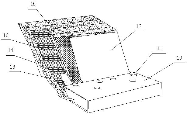
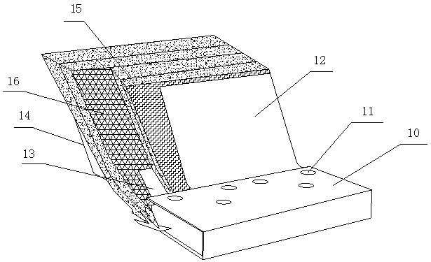
[0021] see figure 1 , the present embodiment is to provide a shield tail seal brush structure that increases the spring plate to improve the resilience, which includes the shell plate 10; the front protective plate 12, the rear protective plate 14 and the front and rear protection plates 12 are fixed in the shell plate 10 by pins 11. There are at least two layers of stainless steel wire groups 15 between the protective plates. In this embodiment, two layers of stainless steel wire groups 15 are fixed inside the shell plate 10, and a stainless steel wire mesh 16 and a spring plate are added between the two stainless steel wire groups 15. 13. The two layers of stainless steel wire groups 15 are separated by a stainless steel wire mesh 16, and the length of the stainless steel wire mesh 16 protruding from the shell plate 10 is close to the length of the second wire layer of the stainless steel wire group 15.

[0022] It is worth mentioning that the spring plate 13 is a spring ste...


PUM


Abstract

The invention discloses a shield tail sealing brush structure for adding a spring plate to improve resilience force, which comprises a shell plate and a front protective plate and a rear protective plate which are arranged on the shell plate. The shield tail sealing brush structure is characterized in that at least two layers of stainless steel wire groups are fixed in the shell plate by pins; the stainless steel wire groups are arranged between the front protective plate and the rear protective plate; the spring plate is also arranged between the two layers of stainless steel wire groups; and the front protective plate, the rear protective plate and the spring plate are fixed in the shell plate by the pins. In the shield tail sealing brush structure, the spring plate is added between the two stainless steel wire groups, so the resilience force of the stainless steel wire groups is increased, the service life of the stainless steel wire groups is prolonged, shield tail sealing is prevented from losing efficacy in the using process, the construction quality and construction process are ensured, the time of repairing or replacing the shield tail sealing brush is reduced simultaneously, and the cost is reduced.

Description

[0001] technical field [0002] The invention relates to a shield tail seal brush structure of a shield machine, in particular to a shield tail seal brush structure with spring plates added to improve resilience. [0003] Background technique [0004] With the development of urban construction in our country, underground rail transit, cross-river tunnels and other underground projects are increasing day by day, and the shield driving distance of tunnels is also getting longer and longer. The shield tail seal of the shield machine is generally composed of 3 shield tail seal brushes, forming two grease compartments, namely the front compartment and the rear compartment, the first two are short shield tail brushes, and the third is long shield tail brushes. During shield excavation, the segment is stationary and the shield body is moving continuously, so there is relative sliding between the shield tail and the installed segment. In order to prevent external sewage and sedimen...

Claims


Application Information

Patent Timeline
IPC IPC(8): E21D9/06
Inventor 贾明
Owner 昆山众备机械设备有限公司
Learn More