
Spindle liner component for turning machines

Active Publication Date: 2015-08-06
DRUST CRAIG
View PDF10 Cites 0 Cited by
  • Summary
  • Abstract
  • Description
  • Claims
  • Application Information

AI Technical Summary

Benefits of technology

The invention involves adding a spring / resilient member to a device or system. This can be a helical spring or a cylindrical insert made of rubber or steel wire. The addition of the insert or stiffening of the spring can increase its resilience and allow it to flex while still performing its functions. The technical effect of this invention is to enhance the flexibility and resilience of the device or system.

Problems solved by technology

However, if the diameter of the work-piece is significantly smaller than the inner diameter of the spindle, the work-piece may be substantially unsupported along the length of the spindle and may be subjected to bending as a result of centrifugal forces, which cause a whipping and / or vibration (with noise) of the unsupported length of the work-piece.
This makes it difficult to machine properly and to meet the required tolerances.
Modern lathes, capable of operating at very high RPM rates (typically 5000-10000 RPM) may, disadvantageously, have to be run at lower than preferred speeds to obviate such problems.
Even with such liners vibration of the work piece can be a problem as the work-piece is not evenly supported; for example, small diameter work-pieces typically flex and whip to boundaries of spindle liner reduction tube / bushing; causing damage to the spindle liner, leading also to work-piece material being scrapped as a result of damage.
Vibration of the entire work-piece becomes more of an issue as the diameter / length of material increases (therefore the mass of material increases to be contained).
All of these problems are typically reduced by limiting machining speed; however, this adversely affects the attainment of required manufacturing tolerances.

Method used


Image

  • Spindle liner component for turning machines
  • Spindle liner component for turning machines
  • Spindle liner component for turning machines

Examples


first embodiment

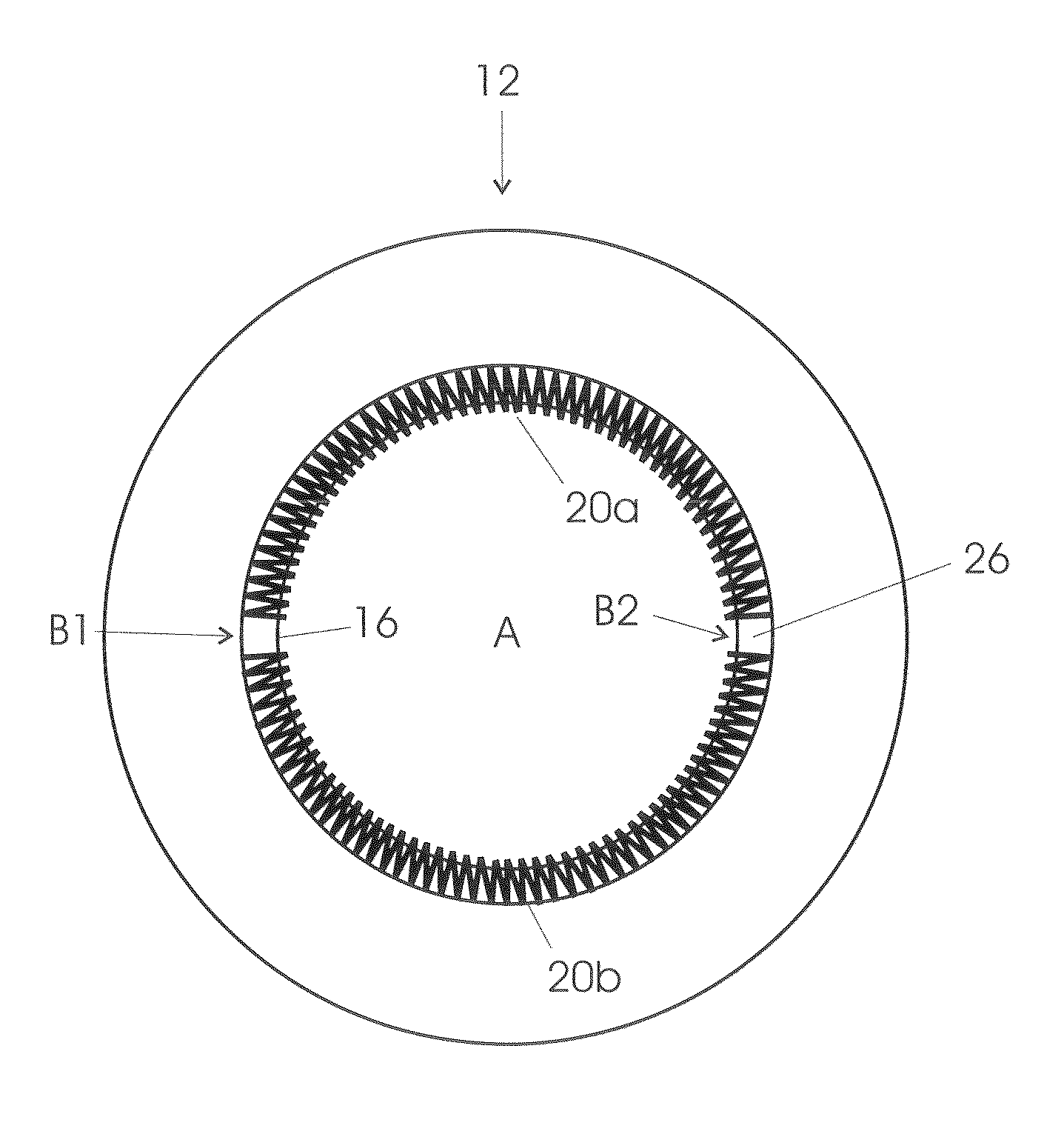
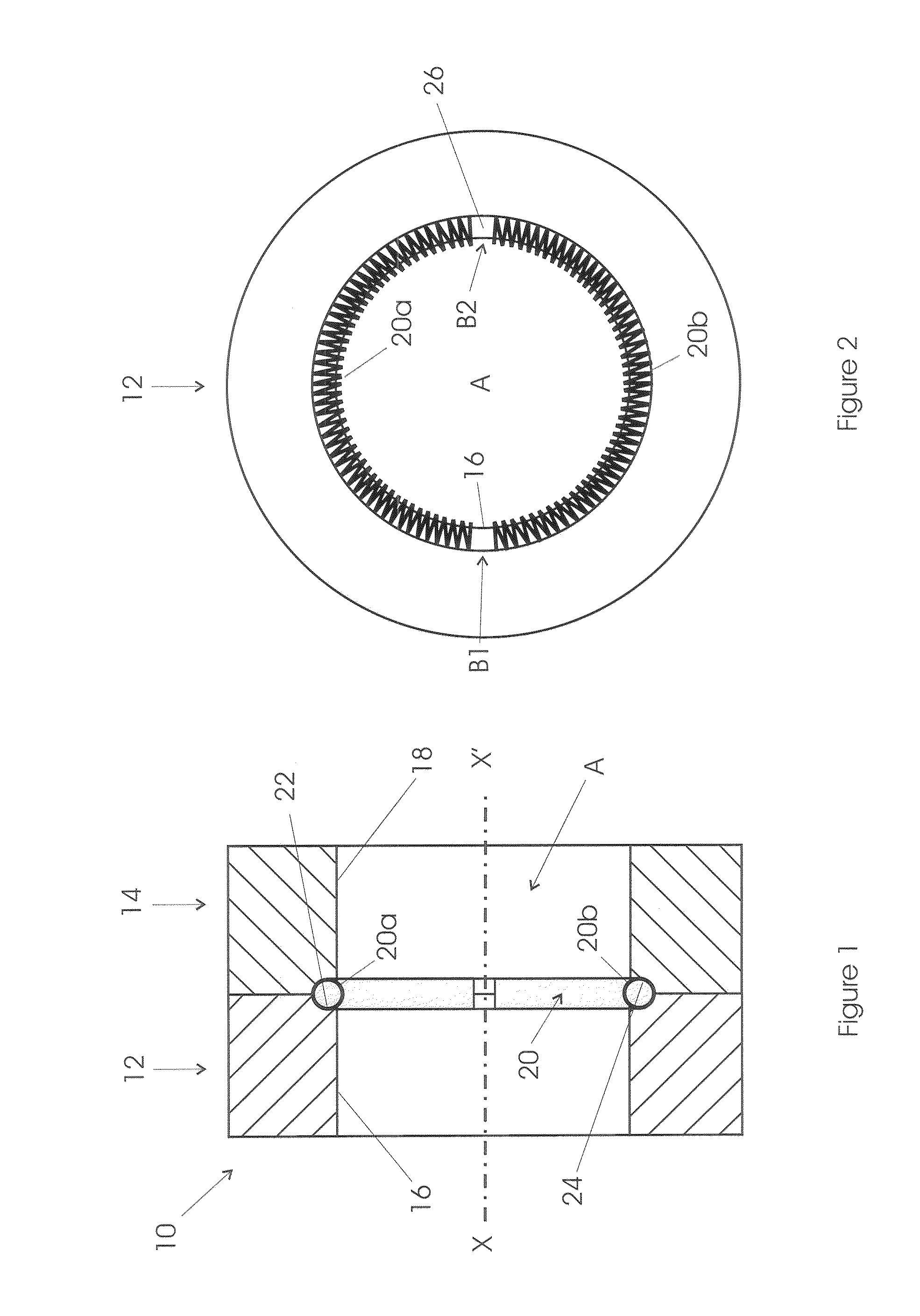
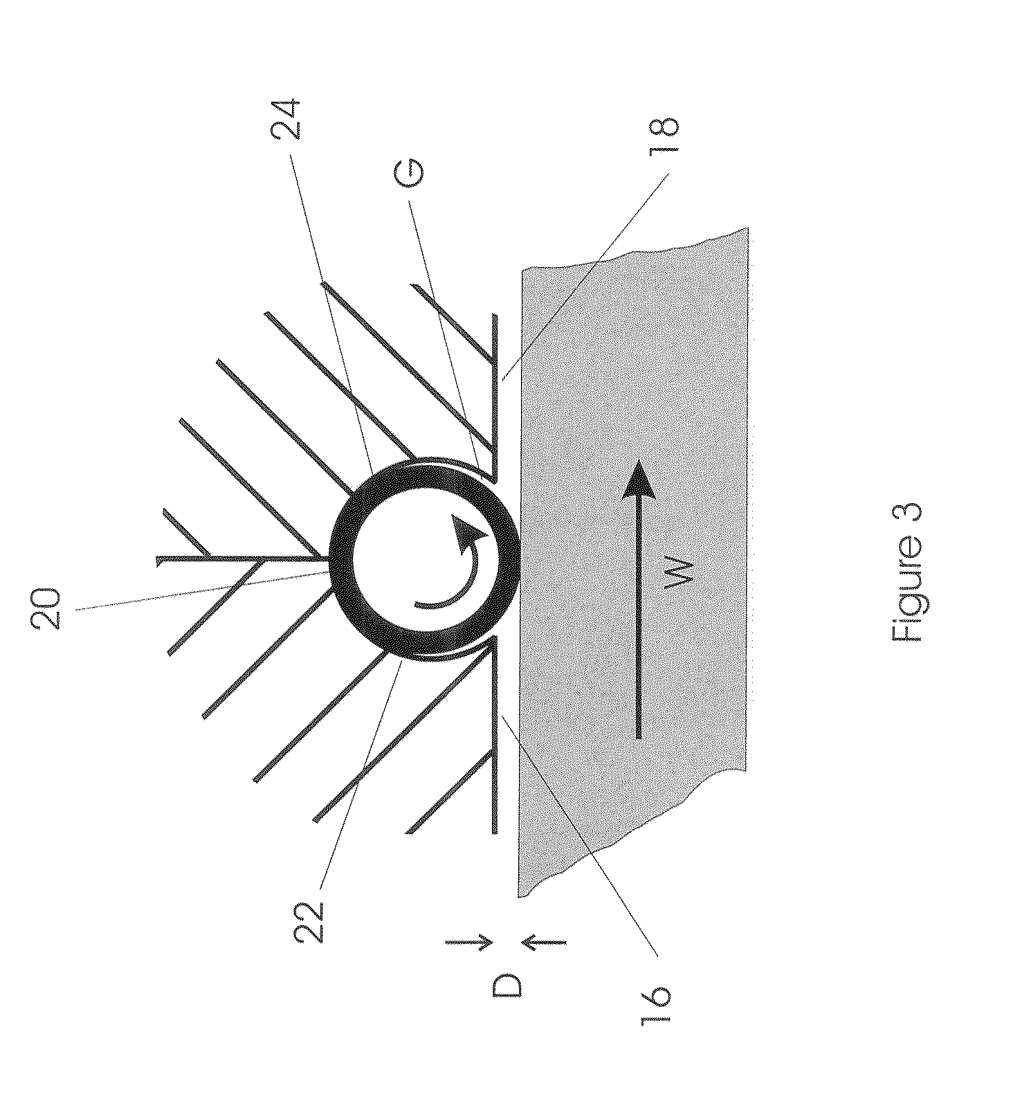
[0031]The invention will now be described in detail by reference to FIGS. 1 to 7. FIGS. 1 and 2 show a side view and an end view of a support member (10) according to the present invention. The support member (10) is cylindrical in shape; with a central aperture A (sized to accept a work-piece); and is dimensioned to closely fit (slip-fit) within the hollow spindle of a turning machine. The support member (10) comprises a first disc (12) and a second disc (14) each with a central aperture that in use form part of said central aperture (A) and where in use the discs (12, 14) are held in side-by-side / adjacent configuration by bolts or pins that pass through suitably sized and positioned holes (not shown). The inner face of each disc (12, 14) has an arc-shaped groove (22, 24), located adjacent the inner face (12,14) of each disc, as shown for the first disc (12) in FIG. 2; each of these grooves (22, 24) has a similar arcuate cross-section (see FIG. 1) such that in use the grooves (22, ...

second embodiment

[0033]In the invention (see FIG. 4) the continuous (circular) grooves (22, 24) in the first and second disc are replaced by three arcuate groove portions (30a, 30b, 30c); each of these arcuate grooves having the same arcuate cross-section such that in use the arcuate grooves provide means (channels) of holding three helical springs (32a, 32b, 32c) in a generally circular orientation. This advantageously allows pin holes (34) (for holding the two discs in side-by-side position using pins) to be located in the gap between the three arcuate grooves. Such an arrangement is favoured when the aperture A is relatively large compared to the bore of the hollow spindle of the turning machine.

third embodiment

[0034]FIGS. 5 and 6 show a side view and an end view of a support member (40) according to the present invention. The support member (40) is cylindrical in shape; with a central hexagonal aperture B (sized to accept a work-piece); and is dimensioned to closely fit (slip-fit) within the hollow spindle of a turning machine. The support member (40) comprises a first disc-assembly (42) and a second disc (44) each with a central aperture that in use form part of said central aperture (B) and where in use the disc (44) and disc-assembly (42) are held in side-by-side / adjacent configuration by bolts or pins that pass through suitably sized and positioned holes (not shown). The first disc-assembly (42) comprises three equal-sized disc segment portions (42a-42c). The inner face of each disc segment (42a-42c) has two linear and interconnected or separate grooves (52), as shown in FIG. 6; the inner face of the second disc (44) has six linear and interconnected or separate grooves (54). Each of ...


PUM

PropertyMeasurementUnit
Thicknessaaaaaaaaaa
Thicknessaaaaaaaaaa
Thicknessaaaaaaaaaa

Abstract

A work-piece support member forming part of a spindle liner for use within the hollow spindle of a turning machine comprising: a disc dimensioned to fit closely within the hollow spindle, having a central aperture (A) sized to accept a work-piece; holding at least one helical spring (20) positioned adjacent to the aperture (A); such that in use the axis of said spring is held perpendicular to the axis of said work-piece such that part of the side walls of said spring or springs (20) abut against said work-piece and thereby firmly support said work-piece as it rotates with the hollow spindle about the axis of said hollow spindle.

Description

TECHNICAL FIELD[0001]The present invention relates to an improved liner and / or component thereof (support member) for use within a hollow spindle of a turning machine; especially a CNC lathe.BACKGROUND ART[0002]Turning machines, such as lathes, are widely used to manufacture parts from work-pieces of various shapes (cross section). Modern CNC lathes allow rapid and automated production of machined parts. They normally feed such a work-piece through a hollow spindle that rotates with an associated lathe chuck; and is located behind the chuck. This allows a rotating work piece to be progressively (intermittently) advanced through the chuck towards the lathe cutting tools. When the machine is used to cut a work-piece having a diameter that is only slightly smaller than the inner diameter of the spindle, the work-piece is in-part supported by the spindle. However, if the diameter of the work-piece is significantly smaller than the inner diameter of the spindle, the work-piece may be sub...

Claims


Application Information

Patent Timeline
IPC IPC(8): B23B13/08
CPCB23B13/08B23B2260/136B23B2260/026Y10T82/2595B23B13/123B23Q3/12
Inventor DRUST, CRAIG
Owner DRUST CRAIG
Learn More