
Family car exhaust manifold

A technology for exhaust manifolds and cars, which is applied to exhaust devices, air quality improvement, noise reduction devices, etc., can solve the problems of difficult processing, high equipment requirements, large factory investment, etc., and achieves easy processing, simple processing equipment, The effect of the simple structure of the parts

Inactive Publication Date: 2011-05-25
王根良
View PDF0 Cites 1 Cited by
  • Summary
  • Abstract
  • Description
  • Claims
  • Application Information

AI Technical Summary

Problems solved by technology

[0002] In the existing automobile engineering technology, the automobile exhaust pipe is a common device, which usually includes an air intake pipe, a catalytic converter, and an air outlet pipe; there are four air intake pipes, and the downstream of the air intake pipe is connected with a catalytic converter, and the catalytic converter A catalyst is arranged in the middle; the downstream of the catalytic converter is connected with an air outlet pipe; the air intake pipe, catalytic converter and air outlet pipe are integrated, and are formed by one stamping of a mold; after the automobile exhaust gas passes through the automobile exhaust pipe, harmful substances It can be basically absorbed; it can reduce the pollution of automobile exhaust to the environment; however, the processing cost of the automobile exhaust pipe with this structure is high, the equipment requirements are high, and the processing is difficult; the price of a pair of stamping dies reaches hundreds of thousands; Special stamping machine tools are required, so the factory needs to invest heavily

Method used


Image

  • Family car exhaust manifold
  • Family car exhaust manifold
  • Family car exhaust manifold

Examples


Embodiment Construction

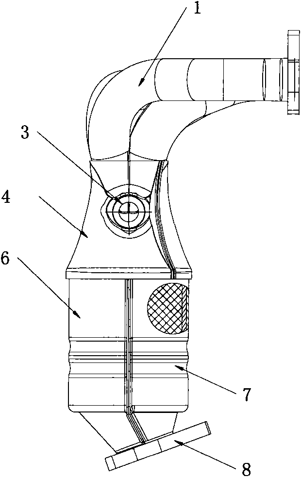
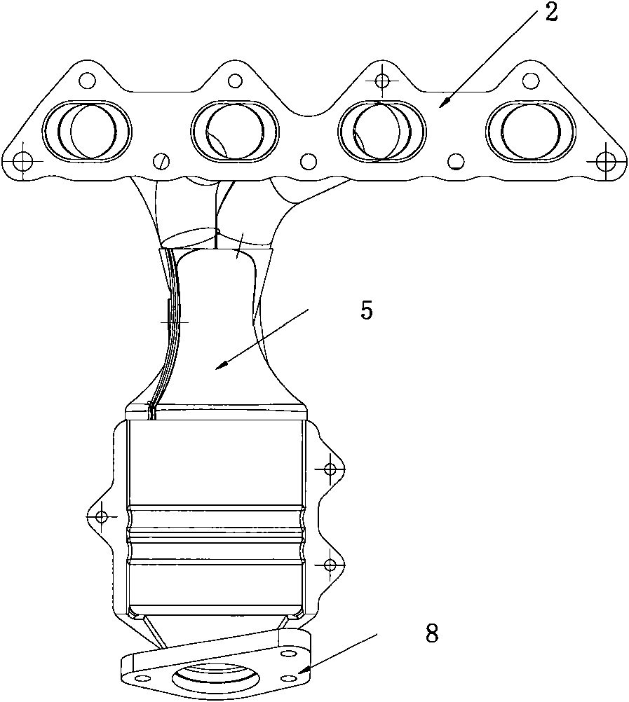
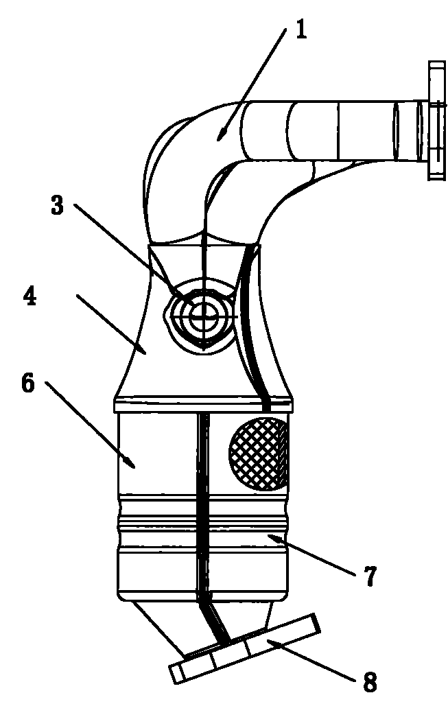
[0014] Such as figure 1 , 2 The shown exhaust manifold of a family car of the present invention comprises an intake pipe 1, a catalytic converter, and an outlet pipe; there are four intake pipes 1, and the downstream of the intake pipe 1 is connected with a catalytic converter, so The catalytic converter is provided with a catalyst; the downstream of the catalytic converter is connected with an air outlet pipe; the air intake pipe 1, the catalytic converter, and the air outlet pipe are independent and formed by welding; the catalytic converter includes a catalytic converter upper cover 14, Catalytic converter upper cover II 5, catalytic converter lower cover I 6, catalytic converter lower cover II 7; said catalytic converter upper cover I 4, catalytic converter upper cover II 5 butt welding; said catalytic converter lower cover I 6, catalytic converter The lower cover II 7 is butt welded; the cavity formed by the lower cover I 6 of the catalytic converter and the lower cover ...


PUM


Abstract

The invention discloses a family car exhaust manifold which comprises air inlet pipes, a catalytic converter and an air outlet pipe, wherein the number of the air inlet pipes is 4; lower reaches of the air inlet pipes are connected with the catalytic converter; catalyst is arranged inside the catalytic converter; the lower reach of the catalytic converter is connected with the air outlet pipe; the air inlet pipes, the catalytic converter and the air outlet pipe are independent and formed by welding; the catalytic converter comprises an upper cover I, an upper cover II, a lower cover I and a lower cover II; the upper cover I and the upper cover II are subjected to butt welding; and the lower cover I and the lower cover II are subjected to butt welding. In the technical scheme provided by the invention, the air inlet pipes, the catalytic converter and the air outlet pipe are independent, the catalytic converter comprises the upper cover I, the upper cover II, the lower cover I and the lower cover II, the upper cover I and the upper cover II are subjected to butt welding, and the lower cover I and the lower cover II are subjected to butt welding, therefore, the part structure is simpler and is easier to process, and required processing apparatuses are simple.

Description

technical field [0001] The invention relates to an automobile exhaust manifold, in particular to an exhaust manifold of a family car with simple structure and easy processing, belonging to the technical field of automobile engineering. Background technique [0002] In the existing automobile engineering technology, the automobile exhaust pipe is a common device, which usually includes an air intake pipe, a catalytic converter, and an air outlet pipe; there are four air intake pipes, and the downstream of the air intake pipe is connected with a catalytic converter, and the catalytic converter A catalyst is arranged in the middle; the downstream of the catalytic converter is connected with an air outlet pipe; the air intake pipe, catalytic converter and air outlet pipe are integrated, and are formed by one stamping of a mold; after the automobile exhaust gas passes through the automobile exhaust pipe, harmful substances It can be basically absorbed; it can reduce the pollution...

Claims


Application Information

Patent Timeline
IPC IPC(8): F01N13/10F01N3/28
CPCY02A50/20
Inventor 王根良沈鹤琦
Owner 王根良
Learn More