
Machine body, and compressor and internal combustion engine using same

A compressor and airframe technology, which is applied in the field of compressors and internal combustion engines, internal combustion engines or compressor bodies, can solve the problems of unbalanced moment, increased friction loss, and failure to achieve balance of the machine, so as to improve rigidity, reduce weight, and reduce difficulty and the effect of the complexity of the structure

Active Publication Date: 2011-05-25
BEIJING SINOCEP ENGINE TECH
View PDF9 Cites 3 Cited by
  • Summary
  • Abstract
  • Description
  • Claims
  • Application Information

AI Technical Summary

Problems solved by technology

[0006] In the machine that has disclosed the crank circular slider mechanism of double circular sliders, between the horizontally arranged piston and the vertically arranged piston (or dynamic balance slider), there is a certain deviation distance for avoiding interference, that is, the distance between the two The central axes are not on the same plane, which makes the machine using the crank circular slider mechanism of double circular sliders have an unbalanced moment and cannot achieve complete balance; while the setting of three circular sliders, sometimes due to the use of a dynamic balance slider to achieve complete balance. Balanced, but the reciprocating parts are added, but the reciprocating parts do not do work externally, which will cause an increase in friction loss

Method used


Image

  • Machine body, and compressor and internal combustion engine using same
  • Machine body, and compressor and internal combustion engine using same
  • Machine body, and compressor and internal combustion engine using same

Examples


Embodiment Construction

[0037] In the following description, numerous specific details are set forth in order to provide a thorough understanding of the present invention. However, the present invention can be implemented in many other ways different from those described here, and those skilled in the art can make similar extensions without violating the connotation of the present invention, so the present invention is not limited by the specific implementations disclosed below.

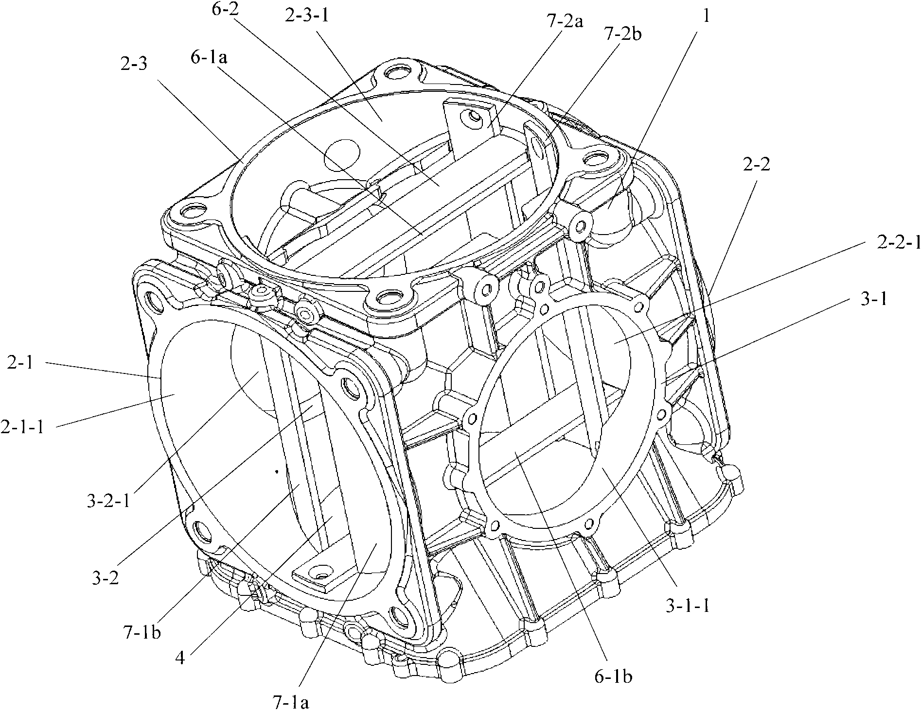
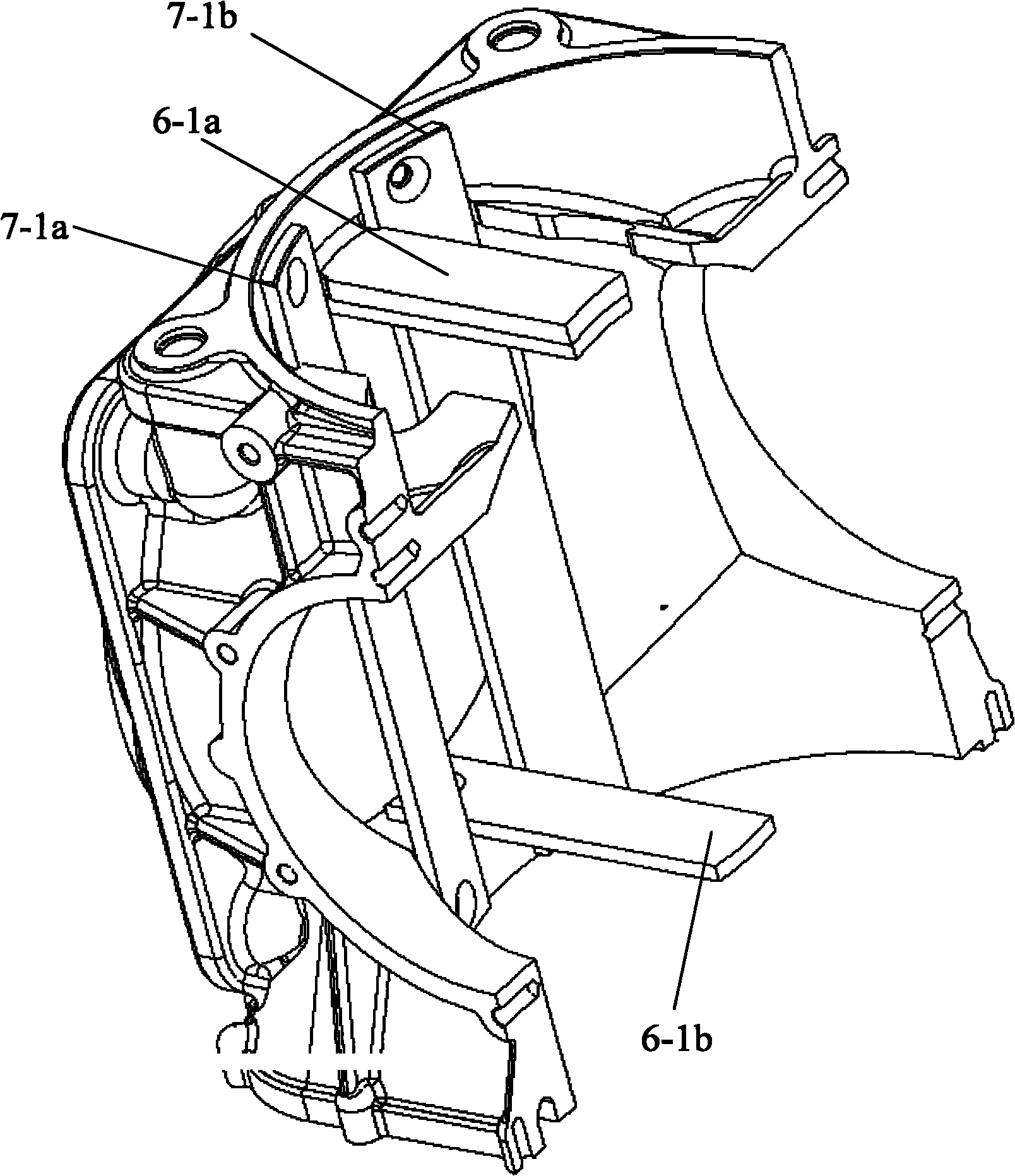
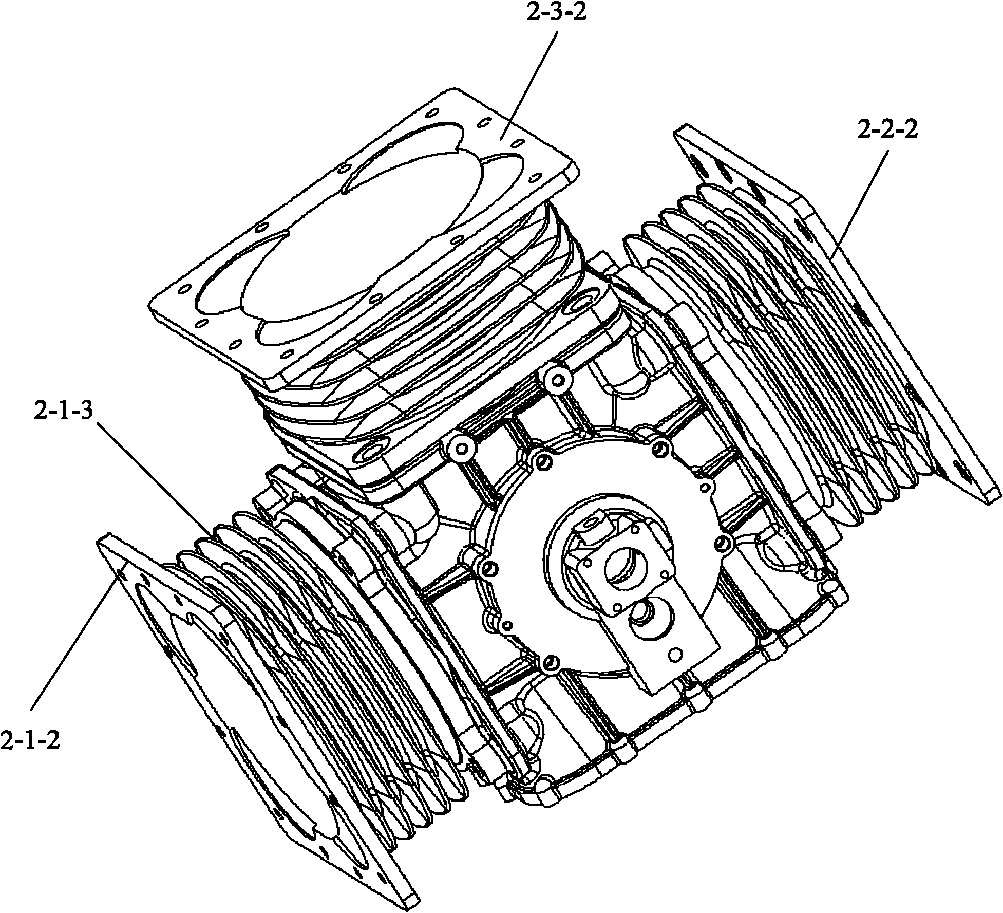
[0038] The body of the present invention will be described in detail below in conjunction with the accompanying drawings. figure 1 is an axonometric view of an embodiment of the body of the present invention; figure 2 for figure 1 The schematic diagram of the body after dissection is shown; image 3 for figure 1 The axonometric view of the shown body after the cylinder is assembled; Figure 4 for image 3 Schematic diagram of the structure of one of the cylinders; Figure 5 Schematic diagram of the structure of the g...


PUM


Abstract

The invention discloses a machine body, which is used in an internal combustion engine or compressor which does not have any connecting rod, and comprises a body, a first air cylinder holder, a second air cylinder holder, a third air cylinder holder, a first primary bearing block, a second primary bearing block and a track, wherein the first air cylinder holder, the second air cylinder holder, the third air cylinder holder, the first primary bearing block, the second primary bearing block and the track are all cylindrical sleeves; a cavity is reserved in the middle of the body, and through holes are formed on the upper, lower, left, right, front and rear walls of the cavity; the first air cylinder holder, the second air cylinder holder, the third air cylinder holder, the track, the first primary bearing block and the second primary bearing block are arranged on the left, right, upper, lower, front and back parts of the cavity respectively; and the central axis of the inner cavity of the third air cylinder, the central line of a horizontal air cylinder and the central line of the inner cavities of primary bearing holes are vertical two by two and meet at one point, and a guide lateral plate is arranged in the cavity of the body. In the machine body of the invention, the reciprocal motion spaces of reciprocally moving parts which move vertically are vertically intercrossed, and a total balance reciprocal motion and rotary motion conversion mechanical can be used. In addition, the invention provides a guide part, a compressor using the machine body and an internal combustion engine using the machine body.

Description

technical field [0001] The invention relates to the technical field of internal combustion engines and compressors, in particular to a machine body applied to internal combustion engines or compressors. The invention also relates to a guide piece and a compressor and an internal combustion engine using the body. Background technique [0002] In a traditional internal combustion engine, the reciprocating motion of the piston is converted into the rotational motion of the crankshaft through the crank-link mechanism, and then the crankshaft drives the corresponding moving parts to output power externally. In the traditional compressor, there is also a crank-link mechanism, through which the rotational motion of the crankshaft is converted into the reciprocating motion of the piston, and the air in the cylinder is compressed by the piston. However, in the crank-link mechanism, due to the existence of the connecting rod, the internal combustion engine and the compressor of the c...

Claims


Application Information

Patent Timeline
IPC IPC(8): F02F1/00F04B39/12F04B39/00
Inventor 黎明黎正中郭立军马玉生
Owner BEIJING SINOCEP ENGINE TECH
Learn More