
Standing bolt for fixed rail of timing chain

A technology for fixing bolts and fixing rails, which is applied in the direction of screws, threaded fasteners, connecting components, etc. It can solve problems such as fastening, difficult fixing of bolts, and poor sealing effect between bolts and timing covers, so as to ensure normal operation , Good sealing, prevent oil leakage

Inactive Publication Date: 2011-05-25
CHERY AUTOMOBILE CO LTD
View PDF6 Cites 12 Cited by
  • Summary
  • Abstract
  • Description
  • Claims
  • Application Information

AI Technical Summary

Problems solved by technology

[0003] The purpose of the present invention is to provide a timing chain rail fixing bolt. When the engine timing cover is integrally cast with the cylinder body and the cylinder head, it is difficult to fasten the rail with the existing bolts. The problem of poor sealing effect of the lid

Method used


Image

  • Standing bolt for fixed rail of timing chain
  • Standing bolt for fixed rail of timing chain
  • Standing bolt for fixed rail of timing chain

Examples


Embodiment 1

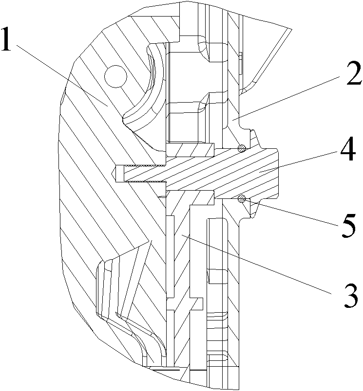
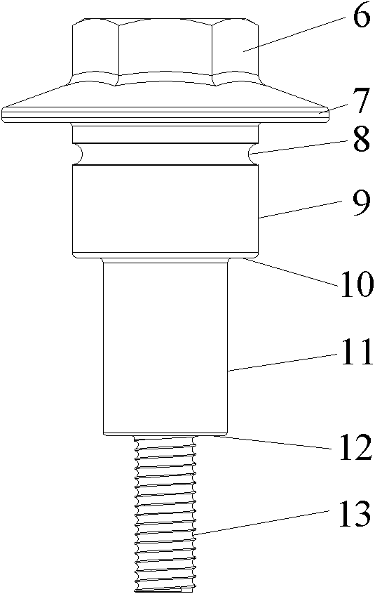
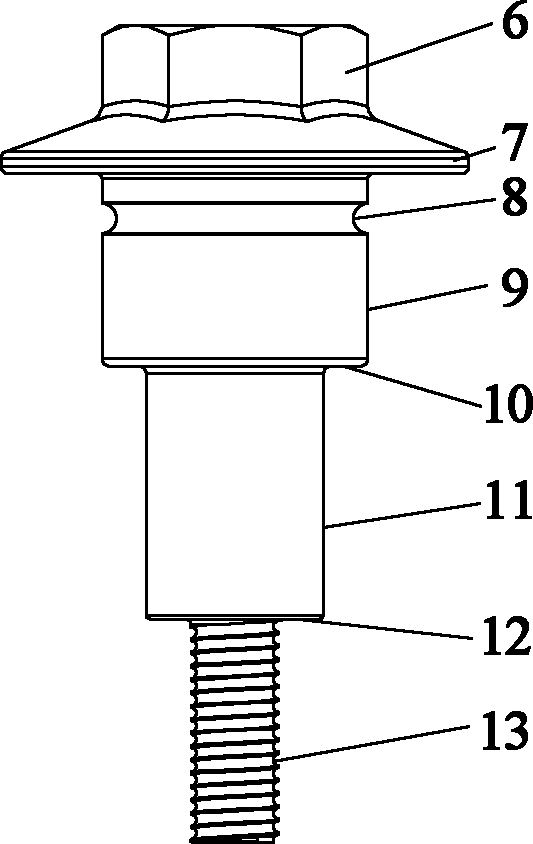
[0012] Example 1, such as figure 1 and figure 2 As shown, a timing chain rail fixing bolt includes a bolt head 6 and a screw rod, and the bolt head is a structure in the shape of a gasket 7 on the side of the screw rod. The outer side of the screw head is in the shape of an outer hexagon. The screw rod is divided into a first screw rod 9, a second screw rod 11 and a third screw rod 13. The first screw rod 9 is provided with an annular groove 8. In order to prevent stress concentration when the bolt is tightened, the described screw rod The distance between the groove on the first screw rod and the washer 7 on the head of the bolt is at least 3 mm. A first step 10 is provided between the first screw 9 and the second screw 11, the diameter of the first screw is greater than the diameter of the second screw, and a step 10 is provided between the second screw 11 and the third screw 13. The second step 12, the diameter of the second screw rod is larger than the diameter of the ...


PUM


Abstract

The invention discloses a standing bolt for a fixed rail of a timing chain, which comprises a bolt head and screw rods, wherein the screw rods are divided into a first screw rod, a second screw rod and a third screw rod; an annular groove is formed on the first screw rod; a first step is arranged between the first screw rod and the second screw rod; the diameter of the first screw rod is greater than that of the second screw rod; a second step is arranged between the second screw rod and the third screw rod; and full threads are formed on the third screw rod. The standing bolt has high sealing effect, and can clamp the fixed rail on an engine easily.

Description

technical field [0001] The invention relates to a fixing bolt, in particular to a timing chain rail fixing bolt on an engine. Background technique [0002] The timing cover is an important part of the engine, which plays the role of sound insulation, noise reduction and sealing. At present, in order to better improve the assembly process of the timing cover and ensure its tightness, the engine timing cover is integrated with the cylinder block and the cylinder head by casting as one. The timing cover is no longer an independent part. This arrangement reduces the assembly of the timing cover and reduces the use of cover bolts, which greatly simplifies the assembly process and has a better sealing effect. But for the timing cover of this arrangement, it is difficult to fix the rail of the timing chain with ordinary bolts, and when the engine is running at high speed, because the rail is not fixed tightly, the chain will drive the rail to the axis of the rail fixing bolt. If ...

Claims


Application Information

Patent Timeline
Patent Type & Authority Applications(China)
IPC IPC(8): F16B35/04F16B35/06F01L1/348
Inventor 霍英贤
Owner CHERY AUTOMOBILE CO LTD
Learn More