
Intelligent constant-voltage high-precision leak detector

A leak detector, high-precision technology, applied in the direction of liquid tightness measurement using liquid/vacuum degree, by measuring the increase and deceleration rate of the fluid, etc., can solve the problems of high clamping pressure, inability to eliminate, random errors, etc., to achieve The effect of eliminating theoretical errors

Active Publication Date: 2011-05-25
付佳
View PDF1 Cites 6 Cited by
  • Summary
  • Abstract
  • Description
  • Claims
  • Application Information

AI Technical Summary

Problems solved by technology

Therefore, as a high-precision measurement, its error sometimes accounts for 0.1-0.5% of the system error is unacceptable
[0012] 1.2 For the analysis in 1.1, it is limited to the calculation and analysis of leakage and pressure changes in the gaseous state equation. It does not consider that the leakage points in the workpiece are pores or sand holes with small gaps. The pressure difference is sensitive. When the atmospheric pressure changes between 200-600Pa, the gap flow rate will change by about 1.55%, which will also cause unacceptable reading errors in pressure measurement.
[0013] 2. Random error
[0014] 2.1 When the internal volume of workpieces is different, such as casting workpieces, the difference in internal volume will also cause measurement errors in a system that uses the average volume of a measured piece as a reference calculation value; and because this error cannot be recognized in the current system, can not be eliminated
[0015] 2.2 The internal volume of the detection system is different due to the different deformation of the seal. The error principle is the same as item 2.1. However, due to the difference in pressure when clamping the workpiece, the clamping pressure is large, and the deformation of the seal is large. Conversely, the deformation is small. design eliminates that some cannot
[0016] 2.3 Random changes in inflation pressure. Although the detection pressure regulating valve can maintain a certain accuracy, a small amount of deviation will occur in practice. The existing leak detector adopts the default method and does not need to be adjusted, resulting in random error

Method used


Image

  • Intelligent constant-voltage high-precision leak detector
  • Intelligent constant-voltage high-precision leak detector

Examples


Embodiment Construction

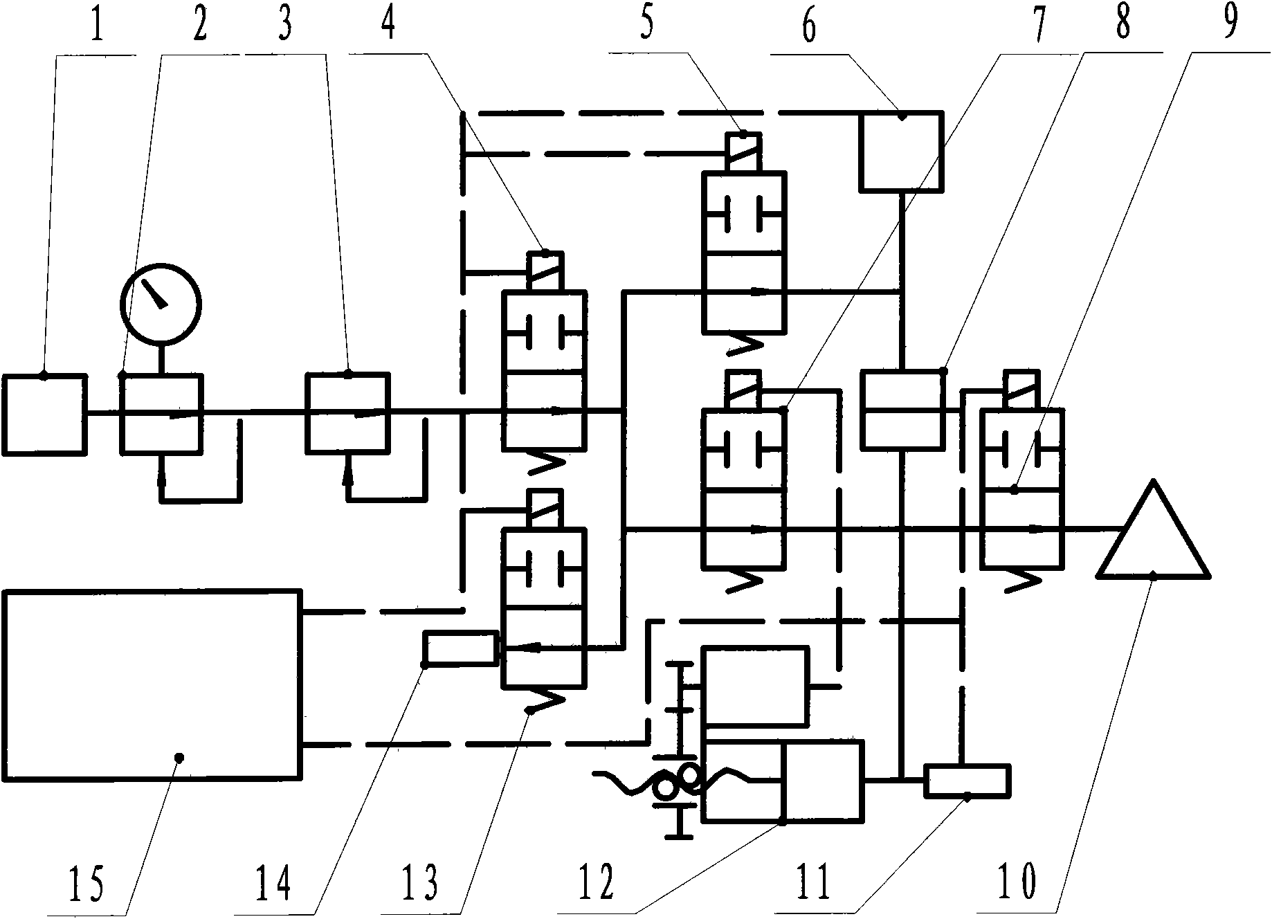
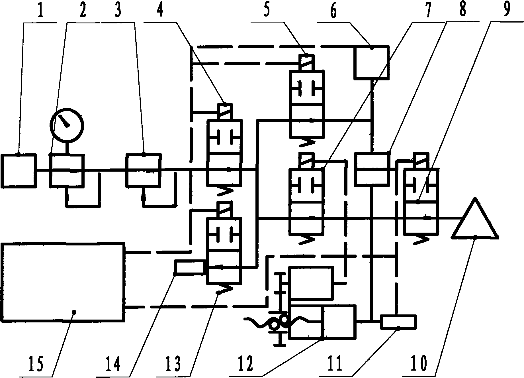
[0021] Combine below figure 1 , to describe a specific embodiment.

[0022] The compressed gas in the pressure gas source 1 in the figure is set by the pressure setting of the pressure regulating valve 2 to set the working pressure for the detection pressure regulating valve 3 . The detection pressure regulator valve 3 is used to control the gas pressure passing through the charging valve 4, that is, the system pressure of the detection system. When the system is started, the system first performs a self-test. During the self-test, the self-test valve 9 is closed, and the gas passage between the system and the device under test 10 is cut off, and then the inflation valve 4 is opened to fill the internal system with a test pressure regulator valve. 3 Set the pressure of the gas. After the inflation is completed, the inflation valve 4 is closed, and the electronic program controller 15 controls the servo barostat 12 to change according to the set value and the set number of ti...


PUM


Abstract

The invention relates to a pressure gas leak detector for airtight containers, in particular to a pressure gas leak detector which maintains the detection pressure as a required detection pressure value constant during detection. A servo type constant pressure device is adopted to track pressure change, so the leak detector can keep the leak detection pressure unchanged, and can correctly meet the technical requirements of constant-pressure leak detection; and most importantly, the detection result is obtained through direct measurement, and the theoretical calculation is not adopted to replace direct measurement any more, thereby directly eliminating various difficultly controlled or measured theoretical errors, systematic errors and random errors. The precision is only affected by the self-precision of the servo type constant pressure device and a leak detection sensor. The self-precision of the sensor or the servo type constant pressure device is optional according to the design ofmeasured objects, is controlled to be less than 0.5 or 0.1 percent of required values, and can fully meet the using requirement of high-precision leak detection.

Description

(1) Technical field [0001] The invention relates to a pressure gas leak detector for a sealed container, in particular to a pressure gas leak detector which keeps the detection pressure at a required detection pressure value during the detection process. (2) Background technology [0002] The current pressure gas leak detectors for sealed containers all adopt the method of converting the volume leakage amount required by the technology into the pressure change with the gaseous equation, use the pressure sensor to measure the pressure change of the detection system, and then use the gaseous state equation to measure the leakage amount and the pressure change. Correspondence to determine whether the tested part is qualified. For example, the patent application number is: 200410072880.X's patent "Airtight Leak Detector for Automatically Calculating Pressurization, Balance, Detection, and Exhaust Time". [0003] Specifically, the inflation method or the vacuum method is used, a...

Claims


Application Information

Patent Timeline
IPC IPC(8): G01M3/32
Inventor 付佳
Owner 付佳
Learn More