
Volume variable air spring auxiliary chamber experiment device and method

An additional air chamber and air spring technology, applied in railway vehicle testing, vehicle suspension/shock absorber testing, liquid/vacuum measurement for liquid tightness, etc. Slowness, unfavorable arrangement of air suspension, etc., to achieve the effect of simple structure, improved driving stability and riding comfort

Inactive Publication Date: 2012-08-29
JIANGSU UNIV
View PDF5 Cites 0 Cited by
  • Summary
  • Abstract
  • Description
  • Claims
  • Application Information

AI Technical Summary

Problems solved by technology

[0002] At present, the test device for the additional air chamber of the vehicle air spring generally has two structural forms. One is to study the stiffness characteristics of the air spring by adjusting the opening of the valve port. The range is small, and the ride comfort of the vehicle is poor
The other is that the volume of the additional air chamber is changed by injecting hydraulic oil. The response to the change of the volume of the additional air chamber is slow, and the addition of oil supply equipment to the traditional additional air chamber not only increases the production cost, but also in the actual installation process. It occupies a certain space, which is not conducive to the reasonable arrangement of the air suspension; the leakage prevention of hydraulic oil in the additional air chamber is also difficult to achieve, and it is easy to cause pollution; the cavitation generated by the hydraulic oil will not only generate vibration and noise, but also damage parts

Method used


Image

  • Volume variable air spring auxiliary chamber experiment device and method
  • Volume variable air spring auxiliary chamber experiment device and method
  • Volume variable air spring auxiliary chamber experiment device and method

Examples


Embodiment Construction

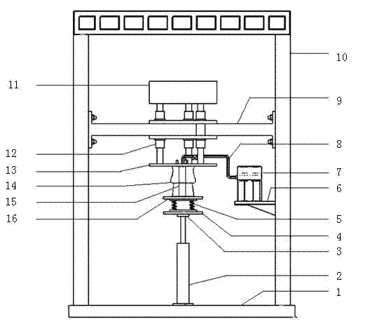
[0014] see figure 1 , the test device of the present invention adopts a gantry frame structure, and the columns 10 of the gantry frame are vertically fixed on both sides of the base 1 by bolts, and the oil cylinder 2 is vertically fixed by bolts in the middle of the base 1, and the upper end of the oil cylinder 2 is connected by bolts to excite vibration. The head 3 and the upper end of the exciting head 3 are connected to the small connecting tray 4 through bolts, the lower end of the coil spring 5 is connected to the small connecting tray 4, and the upper end is connected to the unsprung mass counterweight 16 . The shock absorber 15 and the main air chamber 14 are sequentially connected between the unsprung mass counterweight 16 and the large connection tray 13 by bolts. The main air chamber 14 of the air spring is connected to the additional air chamber 7 through the conduit 8 , the additional air chamber 7 is fixedly placed on the support plate 6 , and the support plate 6 ...


PUM


Abstract

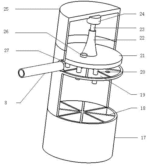
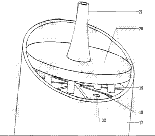
The invention discloses a volume variable air spring auxiliary chamber experiment device and a volume variable air spring auxiliary chamber experiment method. Inner cavities of a cylindrical shell of an auxiliary chamber are eight sector cylinder chambers with same volume, which are separated by sector plates circumferentially; a clapboard is enclosed on the upper end face of the eight sector cylinder chambers, and is provided with eight small holes opposite to the eight sector cylinder chambers; a movable cover plate is arranged on the upper layer of the cylindrical shell, and is provided with a height sensor; the lower end face of the movable cover plate is vertically fixedly connected with eight plunger pistons respectively in sealed fit with the eight small holes, and the lengths of the eight plunger pistons form an arithmetic progression in turn; an air spring system is connected with a computer through a numerical control electrohydraulic servo vibration testing system; and withthe increase of the heights of the eight plunger pistons, the eight sector cylinder chambers are opened in turn, the influence of different volumes of the auxiliary chamber on the characteristics of the air spring is measured, the air spring can obtain a wider rigidity change range, and the running stability and riding comfortability of a sedan are improved.

Description

technical field [0001] The invention relates to an additional air chamber of an air spring in a vehicle air suspension system, in particular to a test device and a test method thereof. Background technique [0002] At present, the test device for the additional air chamber of the vehicle air spring generally has two structural forms. One is to study the stiffness characteristics of the air spring by adjusting the valve opening. The volume of the additional air chamber of the air spring is fixed, and the change of the air spring stiffness The range is small, and the ride comfort of the vehicle is poor. The other is that the volume of the additional air chamber is changed by injecting hydraulic oil. The response to the change of the volume of the additional air chamber is slow, and adding oil supply equipment to the traditional additional air chamber not only increases the production cost, but also increases the actual installation process. It occupies a certain space, which ...

Claims


Application Information

Patent Timeline
Patent Type & Authority Patents(China)
IPC IPC(8): G01M17/04G01M17/10G01M3/02
Inventor 江洪王申旭李超高明宏黄定师
Owner JIANGSU UNIV
Learn More