Fluorescent powder color wheel and projector applying same

A fluorescent pink wheel and fluorescent technology, applied in the field of fluorescent pink wheels, can solve problems such as poor light collection efficiency and light scattering, and achieve the effect of improving light source utilization efficiency

Inactive Publication Date: 2011-05-25
QISDA OPTRONICS (SUZHOU) CO LTD +1
View PDF6 Cites 38 Cited by
  • Summary
  • Abstract
  • Description
  • Claims
  • Application Information

AI Technical Summary

Problems solved by technology

[0004] However, in the above-mentioned prior art, the light generated by the excitation of the fluorescent part will

Method used


Image

  • Fluorescent powder color wheel and projector applying same
  • Fluorescent powder color wheel and projector applying same
  • Fluorescent powder color wheel and projector applying same

Examples


Embodiment Construction

[0021] In order to have a further understanding of the purpose, structure, features, and functions of the present invention, the following detailed descriptions are given in conjunction with the embodiments.

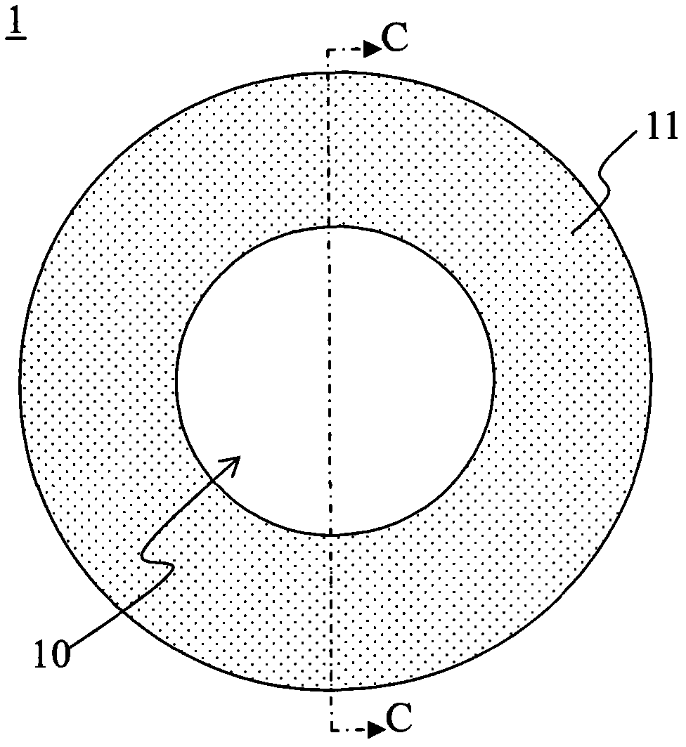
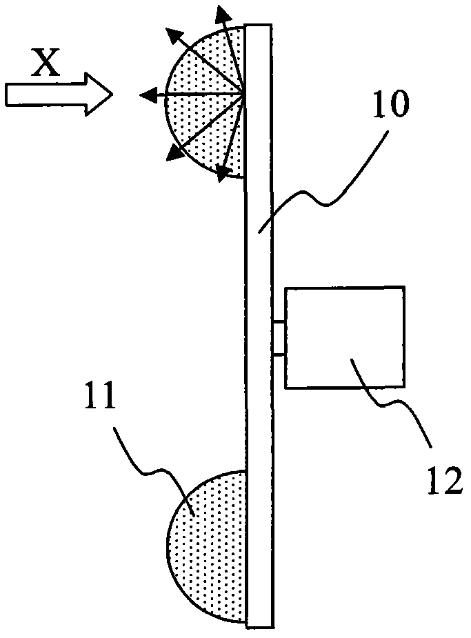
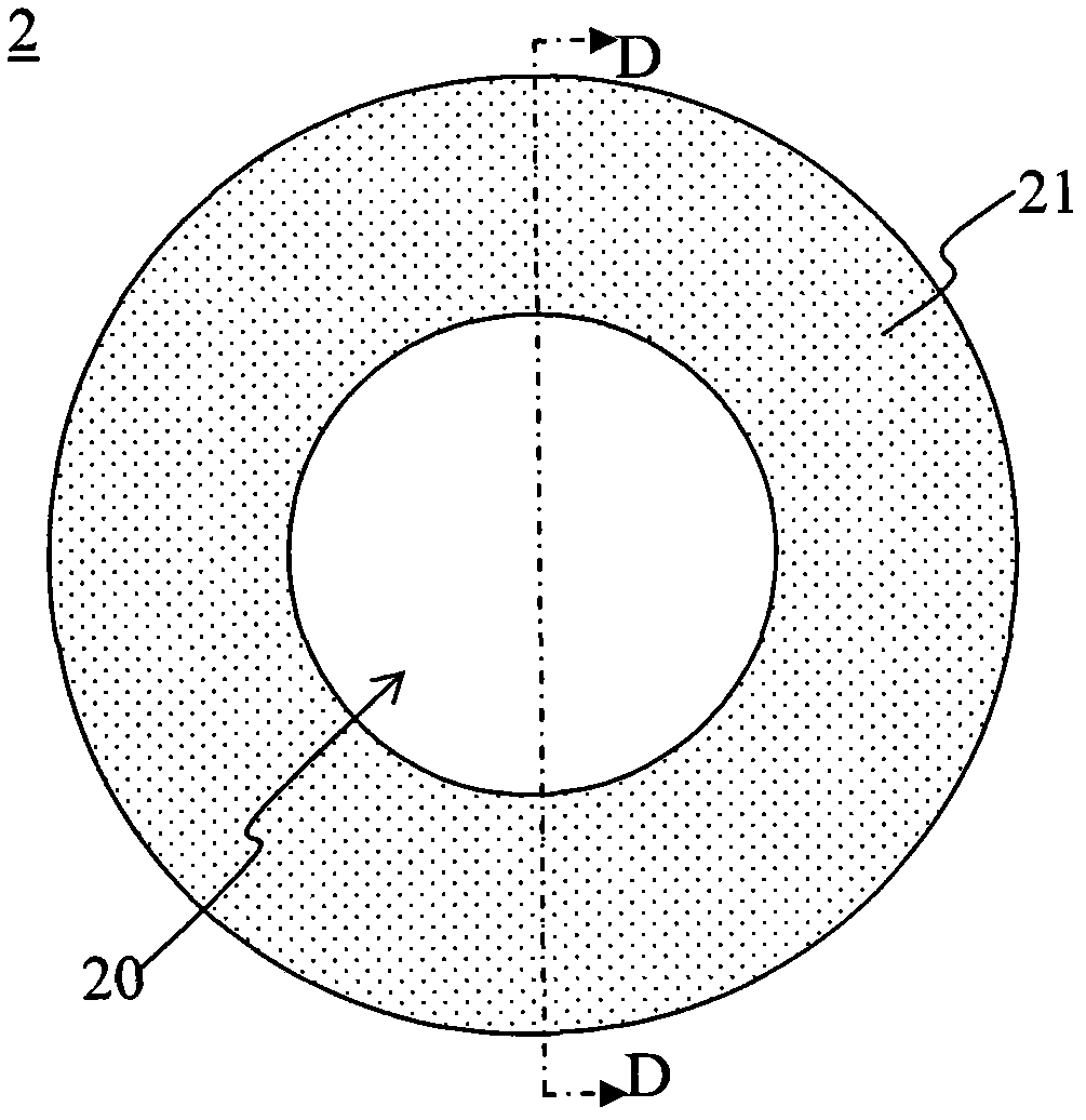
[0022] See image 3 , image 3 It is a schematic structural diagram of the fluorescent pink wheel 3 according to an embodiment of the present invention. The fluorescent pink wheel 3 includes a substrate 30 , a fluorescent part 31 and a light collecting part 33 . The fluorescent part 31 is annularly disposed on the substrate 30, see Figure 1A or Figure 2A . The condensing part 33 is adjacent to the fluorescent part 31 , and the condensing part 33 is used for condensing the light generated after being excited by the fluorescent part 31 . In one embodiment, the condensing part 33 is an epoxy resin (EPOXY) layer covering the fluorescent part 31 . Preferably, the cross-sectional shape of the epoxy resin layer is thick in the middle and thin on both sides to function as...


PUM


Abstract

The invention provides a fluorescent powder color wheel and a projector applying the same. The fluorescent powder color wheel comprises a substrate, fluorescent parts and condensation parts, wherein the fluorescent parts are annularly arranged on the substrate; and the condensation parts are adjacent to the fluorescent parts and are used for converging the light generated after excitation of the fluorescent parts. The light source utilization efficiency of the whole projector system can be improved by the fluorescent powder color wheel provided by the invention.

Description

technical field [0001] The present invention relates to a fluorescent pink wheel, in particular to a fluorescent pink wheel that can improve light-receiving efficiency and a projector using the fluorescent pink wheel. Background technique [0002] Nowadays, more and more projectors use LED (light Emitting Diode, light emitting diode) as a light source, one of which is to use an excitation light source to excite phosphors to emit light of different wavelengths such as red, green or blue as a light source. The color wheel used in this kind of projector is generally coated with phosphor powder that can be excited by LED to emit red, green or blue light on the annular area. When the color wheel is working, the LED light illuminates the fluorescent pink wheel to excite red, green and blue light. , the projector uses the excited light to work. [0003] See Figure 1A and Figure 1B , Figure 1A and Figure 1B is a schematic structural diagram of a traditional reflective fluores...

Claims


Application Information

Patent Timeline
IPC IPC(8): G02B7/00G03B21/14G03B21/00
CPCG02B26/008G03B21/204H04N9/3114
Inventor 简志雄周子翔
Owner QISDA OPTRONICS (SUZHOU) CO LTD
Why Eureka
Try Eureka