Corrosion device for copper clad laminate

A copper-clad plate and equipment technology, applied in the field of copper-clad plate corrosion equipment, can solve the problems of corrosion and rust of the pump, easy splashing of corrosive liquid at the water outlet, etc., and achieve the effect of avoiding dead corners of corrosion and convenient maintenance

Inactive Publication Date: 2011-05-25
SOUTH CHINA UNIV OF TECH
View PDF5 Cites 12 Cited by
  • Summary
  • Abstract
  • Description
  • Claims
  • Application Information

AI Technical Summary

Problems solved by technology

[0002] Chinese utility model patent ZL200720059530.9 discloses a copper-clad plate corrosion device, which includes a liquid storage tank, a pump, and a tank body. The tank body is slightly inclined. The liquid storage tank is located under the water outlet at the lower end of the tank body. It is connected with the water inlet of the pump, and the water outlet of the pump is set roughly horizontally at the high end of the tank body. On the bottom surface of the tank body, there are protrusions arranged in a regular arrangement of different heights. There is a funnel-shaped sewage outlet on the bottom surface of the liquid storage tank. The corrosion The equipment is suitable for the practice teaching of electronic technology in colleges and universities and innovation laboratories, etc. It also has the following defects: the pump is easily corroded and rusted by corrosion leakage, and the water outlet on the tank body is easy to splash corrosion liquid

Method used


Image

  • Corrosion device for copper clad laminate
  • Corrosion device for copper clad laminate
  • Corrosion device for copper clad laminate

Examples


Embodiment Construction

[0030] The present invention will be described in further detail below in conjunction with the accompanying drawings.

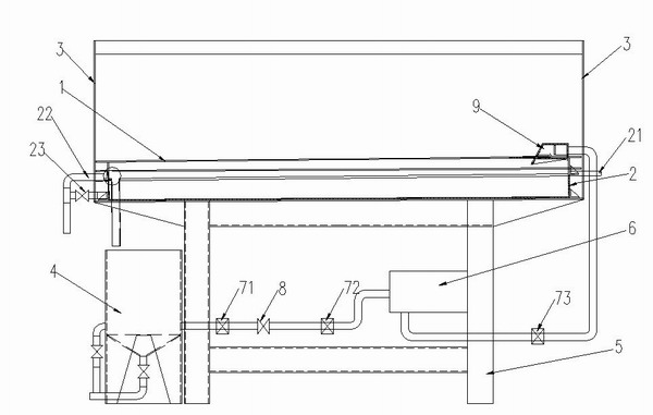
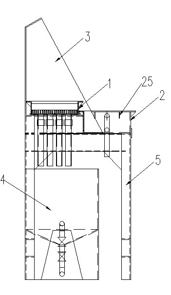
[0031] like figure 1 , figure 2 As shown, a copper-clad plate corrosion equipment includes a bracket 5, a corrosion tank 1, a liquid storage tank 4 and a magnetic centrifugal pump 6, the corrosion tank 1 is slightly inclined, and the liquid storage tank 4 is located under the water outlet 11 at the lower end of the corrosion tank 1 , the liquid storage tank 4 is connected to the water inlet of the magnetic centrifugal pump 6 through a pipeline, and the top of the bracket 5 is in the shape of a step, the front is low and the back is high, the corrosion tank 1 is fixed on the upper step, and the water tank 2 and the water tank 2 are fixed on the lower step. It is roughly equal to the length of the corrosion tank 1, and is arranged in parallel; the high end of the corrosion tank 1 is provided with a bulk fluid box 9, and the fluid fluid box 9 is connected to t...


PUM


Abstract

The invention discloses a corrosion device for a copper clad laminate, which comprises a support, a corrosion groove, a liquid storage box and a magnetic centrifugal pump and is characterized in that a step-like part is arranged above the support, the corrosion groove is fixed on an upper step, a water tank is fixed on a lower step, a bulk liquid box is arranged at the high end of the corrosion groove, and the bulk liquid box is connected with a water outlet of the magnetic centrifugal pump through a pipeline; a water inlet of the magnetic centrifugal pump is arranged in parallel, and the water outlet of the magnetic centrifugal pump is arranged to be downward; and the pipeline connecting the liquid storage box with the water inlet of the magnetic centrifugal pump sequentially comprises a first movable connector, a switch and a second movable connector, and the height of a small section connected with the water inlet of the magnetic centrifugal pump is highest, and higher than the height of the second movable connector. In the corrosion device, the magnetic centrifugal pump is less prone to corrosion caused by leaked corrosion solution, the corrosion solution can not be spilt out on a groove body, and the corrosion device can be applied in manufacturing of a printed circuit board.

Description

technical field [0001] The invention relates to corrosion equipment, in particular to copper clad plate corrosion equipment used for the production of printed circuit boards. Background technique [0002] Chinese utility model patent ZL200720059530.9 discloses a copper-clad plate corrosion device, which includes a liquid storage tank, a pump, and a tank body. The tank body is slightly inclined. The liquid storage tank is located under the water outlet at the lower end of the tank body. It is connected with the water inlet of the pump, and the water outlet of the pump is set roughly horizontally at the high end of the tank body. On the bottom surface of the tank body, there are protrusions arranged in a regular arrangement of different heights. There is a funnel-shaped sewage outlet on the bottom surface of the liquid storage tank. The corrosion The equipment is suitable for the practice teaching of electronic technology in colleges and universities and innovation laboratorie...

Claims


Application Information

Patent Timeline
Patent Type & Authority Applications(China)
IPC IPC(8): G09B25/02H05K3/06
Inventor 周俊生刘友举修建国何璞符玉荷
Owner SOUTH CHINA UNIV OF TECH
Why Eureka
Try Eureka