Slide fastener

A zipper and zipper element technology, applied in the field of zipper, can solve the problems such as inability to insert the cannula 123, inability to insert the cannula 123 fully, and inability to mesh the left and right fastener elements 122.

Active Publication Date: 2012-05-16
YKK CORP
View PDF1 Cites 0 Cited by
  • Summary
  • Abstract
  • Description
  • Claims
  • Application Information

AI Technical Summary

Problems solved by technology

Therefore, there is the following problem: after the first and second sliders 131, 132 are moved to the socket-side end of the element row 122, if the tongue piece 132a of the second slider 132 is not checked every time the first slider 131 When the notch 131a is fitted, the insertion tube 123 cannot be smoothly inserted into the first and second sliders 131, 132.
In such a case, there is also a problem that the insertion tube 123 cannot be fully inserted into the first and second sliders 131, 132, and the left and right element rows 122 cannot be stably engaged.

Method used


Image

  • Slide fastener
  • Slide fastener
  • Slide fastener

Examples


Embodiment 1

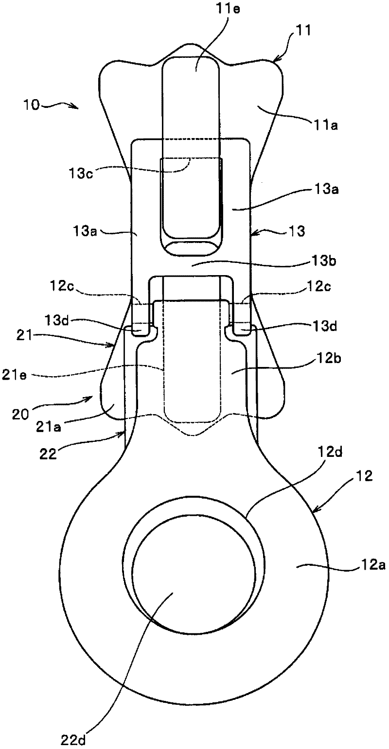
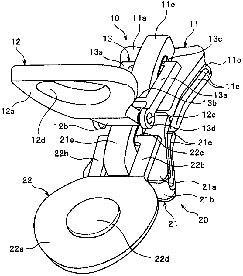
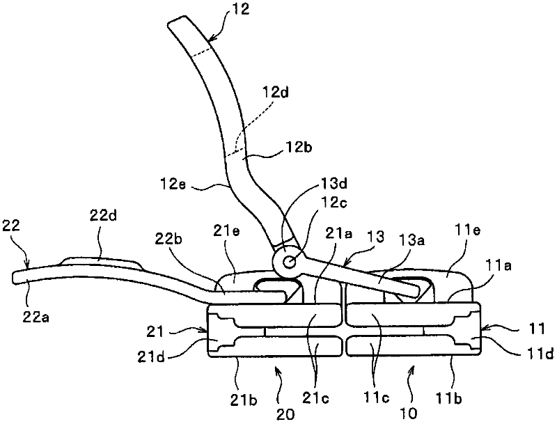
[0146] The slide fastener of Example 1 of this invention is demonstrated. here, figure 1 It is a front view which shows the 1st and 2nd slider in the slide fastener of this Example 1, and the state which handles are engaged. figure 2 It is a perspective view of the first and second sliders in a state where the tab is not engaged, image 3 It is a side view of the first and second sliders in a state where the tab is not engaged.

[0147] in addition, Figure 4 ~ Figure 7 It is a perspective view or a side view of the first and second sliders showing the engaged state of the handle. and, Figure 8 ~ Figure 10 It is a sectional view explaining the operation of inserting the insertion pin into the first and second sliders to mesh the left and right element rows.

[0148] In addition, in the description of the following examples, the tape width direction of the slide fastener in the state where the left and right element rows are engaged is defined as the left-right directio...

Embodiment 2

[0191] Next, the slide fastener according to Example 2 of the present invention will be described. here, Figure 11 to Figure 14 It is a perspective view or a side view which shows the 1st and 2nd slider in the slide fastener of this Example 2, and the state which a handle is engaged.

[0192] The structure of the zipper 41 of the second embodiment is substantially the same as that of the zipper 1 of the first embodiment, except that the second handle 52 of the second slider 50 is connected to the second slider body 51 through the second connecting portion 53. same as above. Therefore, in this Example 2, the parts and members which have the same structure as the slide fastener 1 of the said Example 1 are shown with the same code|symbol, and the description of these parts and members is abbreviate|omitted.

[0193] Furthermore, the referenced in the description of the first embodiment Figure 8 and Figure 9 In the description of the slide fastener of the present embodiment...


PUM


Abstract

The invention provides a slide fastener that has a left and right pair of fastener stringers having element rows arranged thereon, an insert pin and a box pin each formed integrally with one end of a corresponding one of the element rows, and a first slider (10) having a first pull tab (12) and a second slider (20) having a second pull tab (22), the first and second sliders (10, 20) being passed over the element rows with respective rear openings of the first and second sliders opposed to each other. The first and second pull tabs (12, 22) have engaging structures for engaging the first and second pull tabs with each other. When the first and second pull tabs (12, 22) are engaged with each other, the first and second sliders (10, 20) are retained in a state in which the rear openings are opposed to each other. The first pull tab (12) is pivotably connected to a first slider body (11) via a first link section. Engaging the pull tabs of the first and second sliders (10, 20) with each other reliably positions the first and second sliders (10, 20) relative to each other to allow smooth insertion of the pin into the sliders. Thus, the construction improves the easiness of operation of the slide fastener.

Description

technical field [0001] The present invention relates to a reverse-openable zipper in which the first and second sliders are inserted through the element row of the zipper stringer with their back openings facing each other, and more particularly relates to the ability to smoothly insert the insertion tube into the first and second sliders. Among the two sliders, the zipper can easily slide the first and second sliders simultaneously. Background technique [0002] Conventionally, in order to open and close the left and right front sides of clothes, a slide fastener having opening and separating inserts at the lower end of the element row or a slide fastener that can be opened in reverse is often used. [0003] Such a reversible slide fastener for clothing is generally configured such that the element rows can be opened from both ends. For example, in this type of slide fastener, a fastener element row is arranged on each element mounting part of a pair of left and right fast...

Claims


Application Information

Patent Timeline
Patent Type & Authority Patents(China)
IPC IPC(8): A44B19/26
CPCA44B19/262A44B19/26
Inventor 大角美幸近藤祐司桐田美幸
Owner YKK CORP
Why Eureka
Try Eureka