Magnetic side pressure internal control screw spring clutch

A technology of spring clutch and screw rod, which is applied in the direction of magnetic drive clutch, clutch, non-mechanical drive clutch, etc., can solve the problem of inability to achieve high transmission efficiency of gear transmission

Active Publication Date: 2015-06-10
嘉兴美茵钛传动科技有限公司
View PDF8 Cites 8 Cited by
  • Summary
  • Abstract
  • Description
  • Claims
  • Application Information

AI Technical Summary

Problems solved by technology

[0002] Since the birth of automobiles, human beings have never stopped studying the clutches of automobiles. People have developed a variety of automobile clutches. Modern commonly used clutches mainly include friction clutches, hydraulic coupling clutches, electromagnetic clutches, etc., but these Clutches cannot achieve the high transmission efficiency of gear transmission; Wei Boqing's invention patent "201510001309.7 Screw Spring Clutch" is cleverly designed, but it is greatly affected by the centrifugal force of rotation, that is, when the rotation speed of the driven wheel is high, the driven wheel drives The small magnetic block in the rotating wheel may accidentally close the clutch due to excessive centrifugal force. The present invention makes cor

Method used


Image

  • Magnetic side pressure internal control screw spring clutch
  • Magnetic side pressure internal control screw spring clutch
  • Magnetic side pressure internal control screw spring clutch

Examples


Embodiment Construction

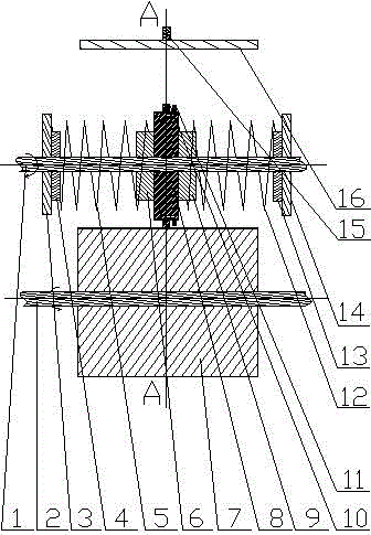
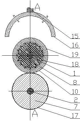
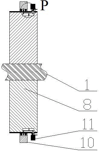
[0021] exist Figure 1-7 In the shown embodiment: the magnetic side pressure internal control screw spring clutch includes a driven shaft 1 with external thread and a driven shaft wheel 8 screwed on the driven shaft 1, and the outer circumference center of the driven shaft wheel 8 has a Passive live wheel 10, passive shaft wheel 8 outer circumferences of passive live wheel 10 sides are symmetrically installed with a plurality of clutch magnetic blocks 35, each clutch magnetic block 35 is connected with a clutch seesaw device 18 by a clutch seesaw bar, each The clutch seesaw device 18 has a clutch seesaw wheel 30 in the area of ​​the inner torus of the passive live wheel 10, and there are a plurality of passive live wheel inner grooves matching the clutch seesaw 30 in the inner torus of the passive live wheel 10 34, the left secondary wheel 6, the left buffer wheel 4, the left retaining wheel 3 and the left spring 5 are arranged on the left side of the passive shaft wheel 8, an...


PUM


Abstract

A magnetic side pressure internal control screw spring clutch comprises a driven shaft with an external thread and a driven shaft wheel screwed on the driven shaft. The outer portion of the center of the outer circumference of the driven shaft wheel is sleeved with a driven free wheel, a plurality of clutch magnetic blocks are symmetrically installed on the outer circumference of the driven shaft wheel on one side of the driven free wheel, each clutch magnetic block is connected with a clutch seesaw device through a clutch seesaw cross rod, each clutch seesaw device is provided with a clutch seesaw wheel in an inner ring surface area of the driven free wheel, and a plurality of driven free wheel inner grooves matched with the clutch seesaw wheel are formed in the inner ring surface of the driven free wheel. Auxiliary wheels, buffer wheels, blocking wheels and springs are positioned on the left side and the right side of the driven shaft wheel, and a semicircular barrel magnetic shoe is installed on one side of the driven free wheel far away from a driving wheel. The magnetic side pressure internal control screw spring clutch is characterized in that the inner diameters, the number and the distribution of the driven free wheel inner grooves correspond to and are matched with the outer diameters, the number and the distribution of the clutch seesaw wheels.

Description

technical field [0001] The invention relates to a magnetic lateral pressure internal control screw spring clutch, which is suitable for clutch transmissions of all automobiles and belongs to the technical field of automobile transmissions. Background technique [0002] Since the birth of automobiles, human beings have never stopped studying the clutches of automobiles. People have developed a variety of automobile clutches. Modern commonly used clutches mainly include friction clutches, hydraulic coupling clutches, electromagnetic clutches, etc., but these Clutches cannot achieve the high transmission efficiency of gear transmission; Wei Boqing's invention patent "201510001309.7 Screw Spring Clutch" is cleverly designed, but it is greatly affected by the centrifugal force of rotation, that is, when the rotation speed of the driven wheel is high, the driven wheel drives The small magnetic block in the rotating wheel may accidentally close the clutch due to excessive centrifu...

Claims


Application Information

Patent Timeline
IPC IPC(8): F16D27/14
Inventor 魏伯卿
Owner 嘉兴美茵钛传动科技有限公司
Why Eureka
Try Eureka