

Magnetically-controlled side pressing type screw rod and spring clutch
A spring clutch and clutch technology, applied in clutches, mechanical drive clutches, belts/chains/gears, etc., can solve problems such as inability to achieve high transmission efficiency of gear transmission, difficulty in miniaturizing clutches, and large magnetic attraction of semi-circular barrel magnetic tiles.
- Summary
- Abstract
- Description
- Claims
- Application Information
AI Technical Summary
Problems solved by technology
Method used
Image

Examples
Embodiment Construction
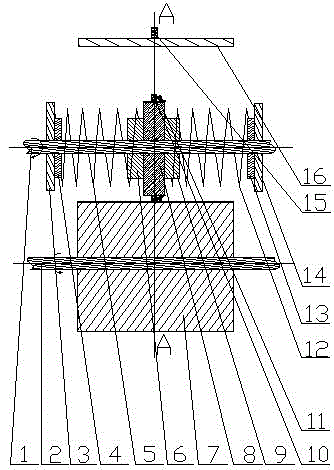
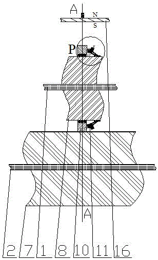
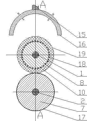
[0021] exist Figure 1-7 In the shown embodiment: the magnetically controlled side pressure screw spring clutch includes a driven shaft 1 with external thread and a driven shaft wheel 8 screwed on the driven shaft 1, and the outer circumference center of the driven shaft wheel 8 has a Passive live wheel 10, a plurality of clutch arm wheels 11 are symmetrically installed on the passive shaft wheel 8 outer circumference of the passive live wheel 10 side, and left auxiliary wheel 6, left buffer wheel 4, left retaining wheel are arranged on the left side of driven shaft wheel 8 3 and left spring 5, there are right auxiliary wheel 9, right buffer wheel 13, right retaining wheel 14 and right spring 12 on the right side of passive shaft wheel 8, and a semicircle magnetic tile 16 is installed on passive live wheel 10 away from driving wheel 7 one side ; It is characterized in that: there is an internal thread in the center hole of the driven shaft wheel 8, and the internal thread of t...
PUM
 Abstract
Description
Claims
Application Information