Method and device for winding metal strip material

A technology of metal belts and cores, applied in transportation and packaging, winding strips, sleeve/socket connections, etc., can solve problems such as problems with coils

Inactive Publication Date: 2011-05-25
SMS DEMAG AG
View PDF10 Cites 12 Cited by
  • Summary
  • Abstract
  • Description
  • Claims
  • Application Information

AI Technical Summary

Problems solved by technology

This out-of-round configuration causes problems in the further processing of the coils

Method used


Image

  • Method and device for winding metal strip material
  • Method and device for winding metal strip material
  • Method and device for winding metal strip material

Examples


Embodiment Construction

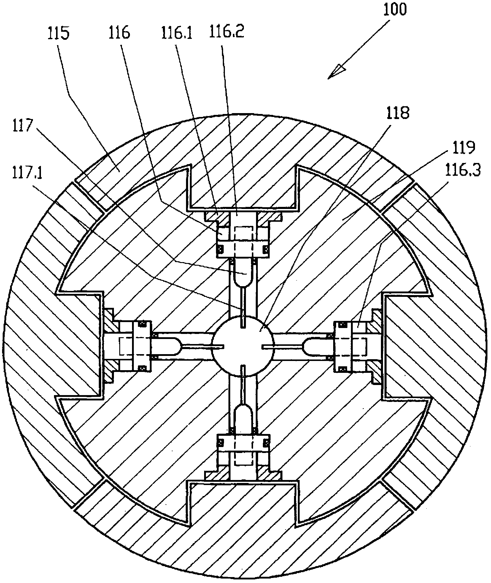
[0045] as in Figures 3 to 5 As shown in FIG. 1 , a coiler mandrel 100 according to the invention is constructed in a winding unit 120 with a cylinder 116 and a balancing cylinder 121 . Cylinder 116 and balancing cylinder 121 move and / or stop segment 115 . For example, cylinder 116 and balancing cylinder 121 are operated hydraulically. Besides oil, other media such as grease can also be used. Cylinder 116 is used to transmit or generate expansion force and movement of section 115 . As shown, the cylinder 116 with its cylinder head 116.1 and with its cylinder piston 116.2 is inserted directly into the spindle body 119 . However, it is also conceivable that the entire cylinder 116 is installed as a unit in the coiler shaft 100 . Preferably, each cylinder 116 is equipped with a position detector 117 to enable the exact position of the cylinder piston 116.2 to be determined and controlled or adjusted. The cable 117.1 of the position detector 117 is sent to the rotary conveyor...


PUM

PropertyMeasurementUnit
thicknessaaaaaaaaaa

Abstract

The invention relates to a method and a decoiler mandrel for winding metal strip material (110), wherein the decoiler mandrel (100) comprises a mandrel body (120), a plurality of radially spreadable segments (115) being disposed about the mandrel body (120), and a plurality of hydraulic cylinders (116) through which the segments (115) are moved radially. In order to also be able to wind the metal strip material utilizing a circular coil eye when the friction is different in the individual cylinders, the invention provides that each cylinder (116) of the plurality is controlled individually.

Description

technical field [0001] The invention relates to a method for winding (Aufwickeln) metal bands (Metalband) with: [0002] - with mandrel body Coiler Shaft (Haspeldorn), [0003] - with a plurality of radially expandable (aufweitbar) or expandable (aufspreizbar) segments arranged around the mandrel body, [0004] - A plurality of hydraulic cylinders by means of which the segments can be moved in radial direction. [0005] Furthermore, the invention relates to a device for winding metal strips. Background technique [0006] In the rolling mill, the metal strip is formed into sheet metal or wound coils (bunds), so-called coils (coils), in order to enable transport and further processing within the factory or at the customer. Coils or metal coils are produced when straight metal strips are wound radially in a coiling device. The metal strip is a product from a hot-rolled strip line (Warmbandstra βe) or a cold-rolled strip line (Kaltbandstra βe). This means that, depending ...

Claims


Application Information

Patent Timeline
Patent Type & Authority Applications(China)
IPC IPC(8): B65H75/24B21C47/30
CPCB65H75/242B21C47/30B21C47/02B65H75/249B65H75/24B65H18/02Y10T279/1024
Inventor M·基平R·弗兰茨
Owner SMS DEMAG AG
Why Eureka
Try Eureka