Ultraprecise turning method of optical lens with incline

A processing method and technology of optical mirrors, applied in the field of optical device manufacturing and ultra-precision machining, can solve problems such as insufficient tool acceleration, tool destructive influence, tool cutting interference, etc., to improve processing efficiency, avoid tool interference, and reduce tool post-processing corner angle effect

Active Publication Date: 2011-06-01
TIANJIN UNIV
View PDF4 Cites 25 Cited by
  • Summary
  • Abstract
  • Description
  • Claims
  • Application Information

AI Technical Summary

Problems solved by technology

When using slow tool or fast tool servo control technology to process large-inclined optical mirrors, due to the influence of curvature changes of large-inclined optical mirrors, when machining the center of rotation area, reverse cutting may occur due to excessive cutting range and insufficient tool acceleration. Phenomenon, leading to tool cutting interference, causing destructive effects on the tool, which seriously affects the real application of the method

Method used


Image

  • Ultraprecise turning method of optical lens with incline
  • Ultraprecise turning method of optical lens with incline
  • Ultraprecise turning method of optical lens with incline

Examples


Embodiment Construction

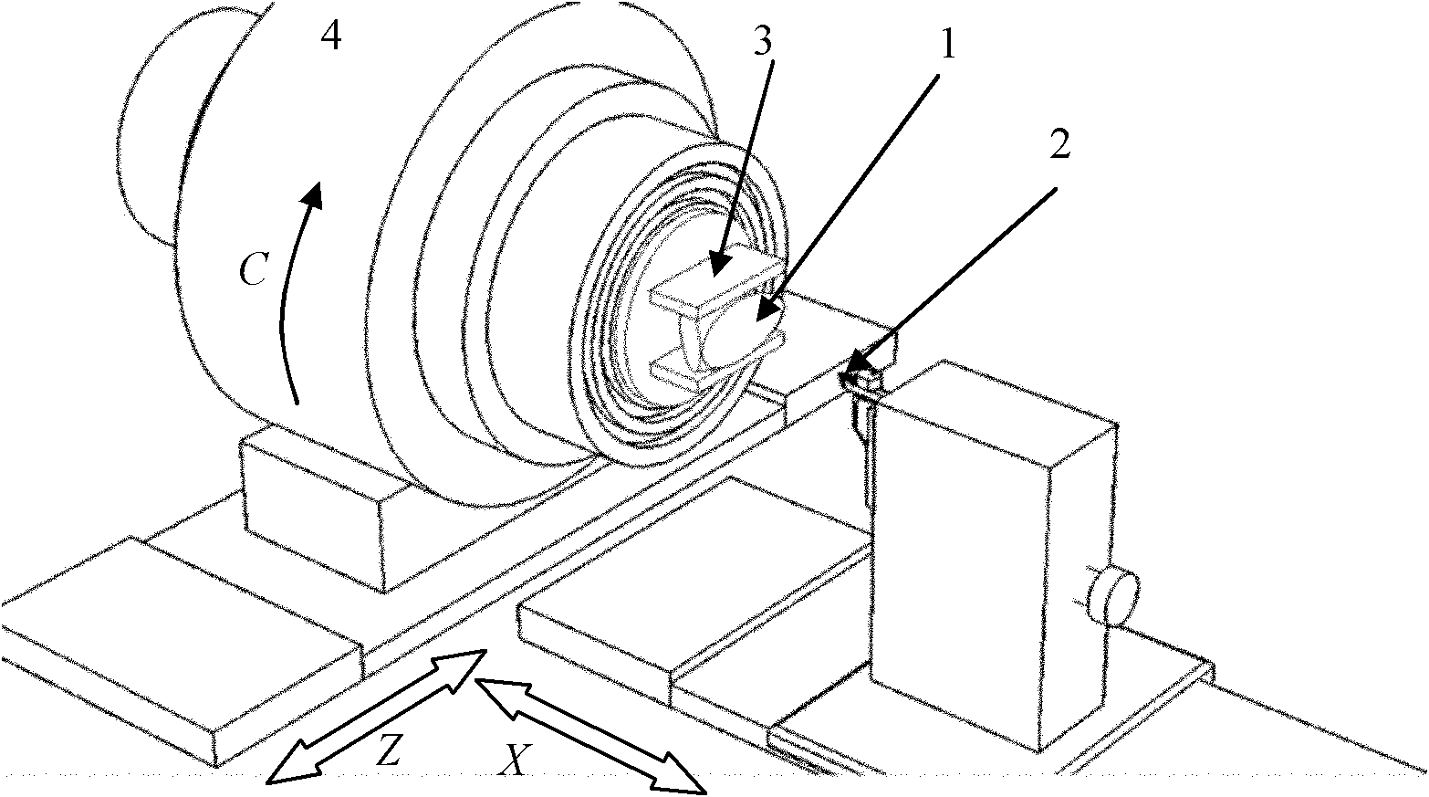
[0021] figure 1 It is a processing schematic diagram of the present invention. In the figure, after the large-slope optical mirror 1 is rough-machined, the slope to be processed is firstly processed into an initial plane, and fixed on an ultra-precision lathe with a fixture 3 . The ultra-precision lathe is a three-axis machining system. The machine tool coordinate system is defined as the Z-axis in the cutting depth direction of the tool, the X-axis in the horizontal feed direction of the tool, and the C-axis in the rotation direction of the spindle 4. In addition, for the convenience of later calculations, the direction perpendicular to the X-axis and Z-axis is defined as the Y-axis direction, and there is no motion axis in this direction. During processing, it is necessary to adjust the initial plane of the processing slope to be perpendicular to the Z axis. The diamond tool 2 processes and shapes the free-form surface of the inclined plane under the coordinated motion of ...


PUM


Abstract

The invention belongs to the technical field of manufacture and ultraprecise processing of optical elements, and relates to an ultraprecise turning method of an optical lens with an incline, which comprises the steps of: taking two datum points on the incline, determining a workpiece initial plane, roughly processing on the incline to be processed; making a fixture and assembling the workpiece on the end face of a processing lathe, regulating the workpiece initial plane to be vertical to the z axis, regulating a workpiece center to be coincide with a main shaft center; and carrying out coordinate conversion to obtain a connecting line of two end points to be coincide with the x axis, calculating a normal angle of the whole curved surface with center coordinates of the two datum points as a new curved surface of the original point, determining a diamond tool rear angle required by processing the curved surface, selecting a proper tool to be assembled on the lathe, carrying out NURBS (Non-Uniform Rational B-Spline) curved surface fitting on the curved surface subjected to the coordinate conversion, and determining the processing path according to a spiral drive line method. The lens surface is leveled by the coordinate conversion, and the tool rear angle required by processing the curved surface is reduced, thus the processing efficiency and the size of the processing workpiece can be increased, and the method is suitable for processing the large-incline optical lens with any gradient and Sag value.

Description

technical field [0001] The invention belongs to the technical field of optical device manufacturing and ultra-precision processing, and relates to a processing method of a large-slope optical mirror. Background technique [0002] The large-slope optical mirror is a common optical device in the architectural optical system, which can realize beam convergence or divergence, and adjust the direction of the optical path, and has the function of shortening the system size and reducing the system structure. The large-slope optical mirror itself has no rotational symmetry axis, and is a typical free-form optical device. The complexity of the shape brings difficulties to processing. [0003] At present, optical devices with rotational symmetry are generally processed by diamond cutting, grinding or polishing techniques, which can meet the requirements of ultra-precision processing. Single-point diamond turning enables single-process processing of optical-quality surfaces without th...

Claims


Application Information

Patent Timeline
Patent Type & Authority Applications(China)
IPC IPC(8): B23B1/00
Inventor 张效栋房丰洲
Owner TIANJIN UNIV
Why Eureka
Try Eureka