End mill

a technology of end mills and grinding plates, which is applied in the direction of metal-working equipment, milling equipment, manufacturing tools, etc., can solve the problems of lowering the thickness precision of the workpiece, deteriorating the surface roughness of the machined surface of the workpiece, and affecting the cutting process. , to achieve the effect of suppressing excessive cutting resistance, suppressing chatter vibrations, and suppressing the lowering of the precision or efficiency of the cutting process

Active Publication Date: 2021-03-18
KAWASAKI HEAVY IND LTD
View PDF2 Cites 0 Cited by
  • Summary
  • Abstract
  • Description
  • Claims
  • Application Information

AI Technical Summary

Benefits of technology

[0005]As one example of a method for suppressing the occurrence of resonant harmonic vibrations, it is conceivable to reduce relief angles of the respective outer peripheral cutting edges of the end mill to facilitate contact between the machined surface of the workpiece and relief faces of the respective outer peripheral cutting edges, thereby obtaining a process damping effect owing to the contact by the relief faces.
[0006]However, in the case of, for example, machining a thin-wall machining wall or machining the surface of a web, if the relief angles are reduced, the force by which the relief faces of the outer peripheral cutting edges press the machined surface of the workpiece in the thickness direction, i.e., cutting resistance, increases. Consequently, there is a risk that forced chatter vibrations of the standing wall itself may occur, or the standing wall may become curved due to the pressing. This may cause lowered precision or efficiency of the cutting process.
[0007]In this respect, Patent Literature 1 describes improving the stability of the cutting process by making the relief angles unequal to each other. However, in the case of the rotary cutting tool of Patent Literature 1, the resonant harmonic vibrations are reduced by making the end cutting edges unequal to each other. Patent Literature 1 discloses nothing about suppressing the chatter vibrations by controlling the relief angles or suppressing the lowering of the precision or efficiency of the cutting process.
[0008]The present disclosure has been made in order to solve the above-described problems. An object of the present disclosure is to provide an end mill that is capable of both suppressing the chatter vibrations and suppressing the lowering of the precision or efficiency of a cutting process.
[0010]According to the above configuration, the first outer peripheral cutting edge whose relief angle gradually increases and the second outer peripheral cutting edge whose relief angle gradually decreases are both used as the outer peripheral cutting edges. This makes it possible to suppress excessive increase in cutting resistance that is applied from the end mill to the surface of a workpiece. Consequently, chatter vibrations can be suppressed, and also, lowering of the precision or efficiency of a cutting process can be suppressed.
[0011]The present disclosure is able to provide an end mill including outer peripheral cutting edges that make it possible to both suppress the chatter vibrations and suppress the lowering of the precision or efficiency of a cutting process.

Problems solved by technology

The chatter vibrations cause, for example, deterioration in the surface roughness of the machined surface of a workpiece or lowered thickness precision of the workpiece.
Consequently, there is a risk that forced chatter vibrations of the standing wall itself may occur, or the standing wall may become curved due to the pressing.
This may cause lowered precision or efficiency of the cutting process.

Method used


Image

  • End mill
  • End mill
  • End mill

Examples


Embodiment Construction

[0016]Hereinafter, a representative embodiment of the present disclosure is described with reference to the drawings. In the drawings, the same or corresponding elements are denoted by the same reference signs, and repeating the same descriptions is avoided below.

[0017][Fundamental Configuration of an End Mill]

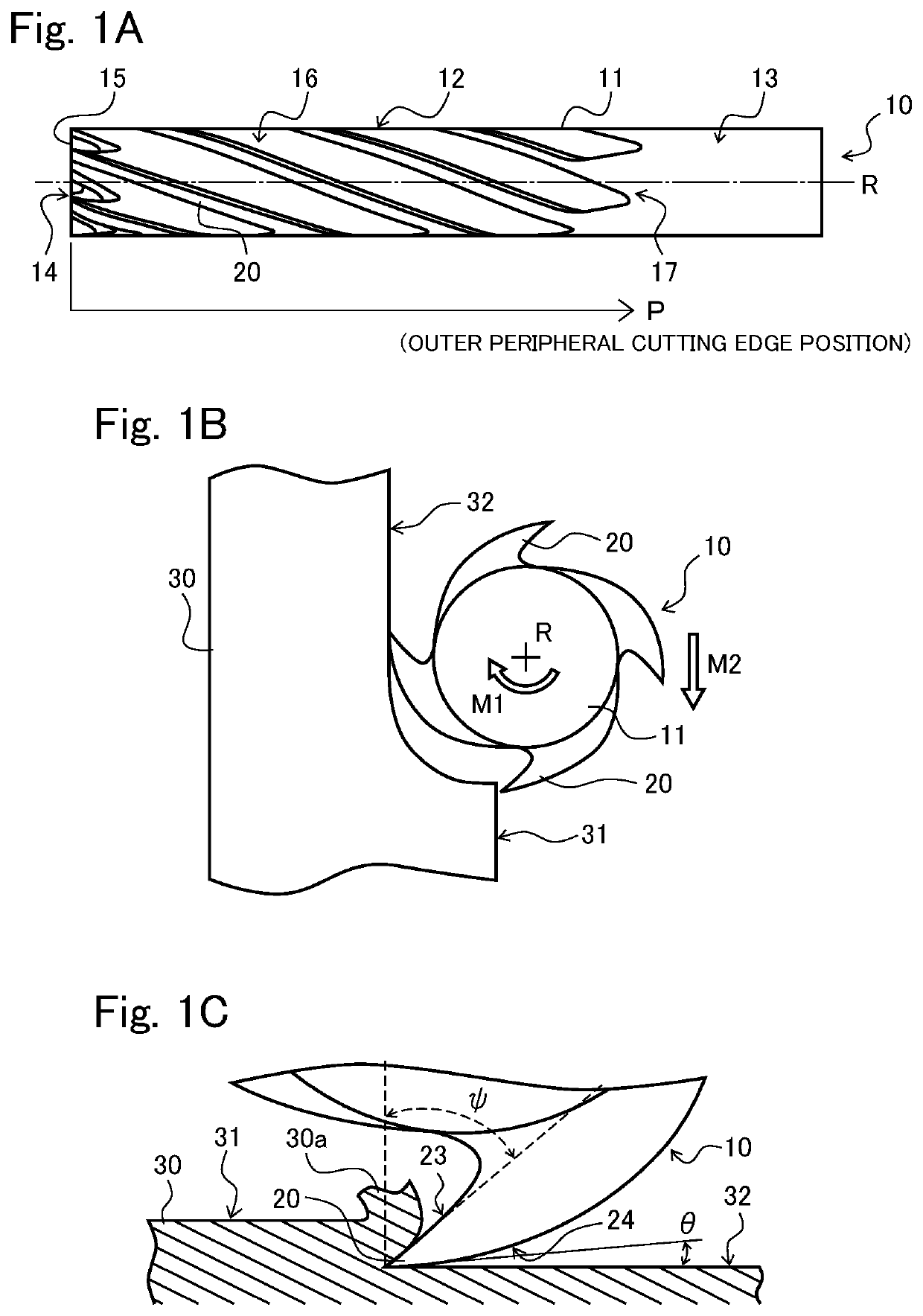
[0018]As shown in FIG. 1A, an end mill 10 includes a columnar tool body 11, a cutting part 12, and a shank 13. The cutting part 12 is positioned on the one end face (first end face) side of the tool body 11, and the shank 13 is positioned on the other end face (second end face) side of the tool body 11. For the sake of convenience of the description, the end face of the side on which the cutting part 12 is positioned is referred to as a bottom face 14.

[0019]The cutting part 12 is provided with cutting edges. Specifically, the cutting part 12 includes a plurality of end cutting edges 15 provided on the bottom face 14 and a plurality of outer peripheral cutting edges 20 provided...


PUM


Abstract

An end mill includes: a columnar tool body that rotates about a center axis; and outer peripheral cutting edges on an outer peripheral surface of the tool body, the outer peripheral cutting edges including a first outer peripheral cutting edge and a second outer peripheral cutting edge. A relief angle θ of the first outer peripheral cutting edge changes to increase in an axial direction of the tool body from a bottom face that is one end of the tool body. A relief angle θ of the second outer peripheral cutting edge changes to decrease in the axial direction from the bottom face.

Description

CROSS-REFERENCE TO RELATED APPLICATION[0001]This application claims priority to and the benefit of Japanese Patent Application No. 2019-169166, filed on Sep. 18, 2019, the entire disclosure of which is incorporated herein by reference.BACKGROUND OF THE INVENTION1. Field of the Invention[0002]The present invention relates to an end mill.2. Description of the Related Art[0003]An end mill, which is a cutting tool, has end cutting edges and outer peripheral cutting edges. The end cutting edges are provided on the end face (bottom face) of the columnar tool body of the end mill, and the outer peripheral cutting edges are provided on the outer peripheral surface of the tool body. It is known that when such an end mill is used in a cutting process, the end mill vibrates during the cutting, which is called chatter vibrations. The chatter vibrations cause, for example, deterioration in the surface roughness of the machined surface of a workpiece or lowered thickness precision of the workpiec...

Claims


Application Information

Patent Timeline
Patent Type & Authority Applications(United States)
IPC IPC(8): B23C5/10
CPCB23C5/10B23C2210/203B23C2210/088B23C2210/0457B23C2210/04
Inventor OTA, TAKUYAZAITSU, MASAYOSHIOTSUKI, NAOHIRO
Owner KAWASAKI HEAVY IND LTD
Why Eureka
Try Eureka