Reciprocating piece for crank round slider mechanism, and internal combustion engine and compressor thereof

A crank circular slider, reciprocating motion technology, applied in the fields of compressors, reciprocating moving parts, and internal combustion engines

Active Publication Date: 2012-09-26
BEIJING SINOCEP ENGINE TECH
View PDF3 Cites 0 Cited by
  • Summary
  • Abstract
  • Description
  • Claims
  • Application Information

AI Technical Summary

Problems solved by technology

[0006] However, in the above mechanism, there is a distance L between the piston and the dynamic balance slider along the axis of the crankshaft, so that the two form a bending moment on the crankshaft, make the whole institution unable to fully balance

Method used


Image

  • Reciprocating piece for crank round slider mechanism, and internal combustion engine and compressor thereof
  • Reciprocating piece for crank round slider mechanism, and internal combustion engine and compressor thereof
  • Reciprocating piece for crank round slider mechanism, and internal combustion engine and compressor thereof

Examples


Embodiment Construction

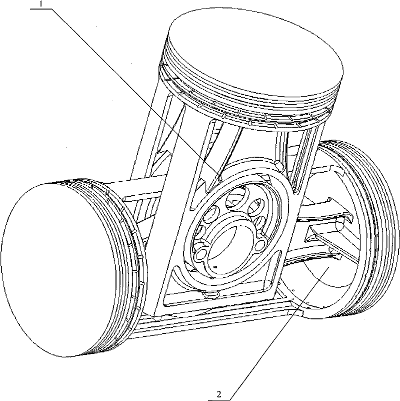
[0027] Please see image 3 , which is a layout diagram of the crank linkage mechanism used by the reciprocating member provided by the embodiment of the present invention. The reciprocating member provided in this embodiment is specifically a piston, image 3 It shows the arrangement structure of the moving parts when the piston is used in a T-shaped three-cylinder crank and slider engine.

[0028] Such as image 3 As shown, the mechanism mainly includes a single-acting piston 1 and a double-acting piston 2 . The two are respectively arranged on reciprocating orbits perpendicular to each other. The single-acting piston 1 moves up and down in the vertical direction, and the double-acting piston 2 moves left and right in the horizontal direction.

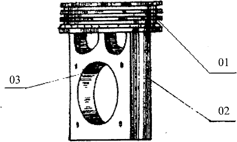
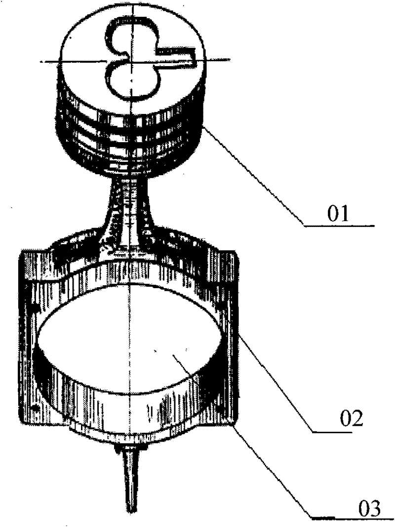
[0029] The single-acting piston 1 will be described in detail below. Please see Figure 4 , which shows a perspective view of a reciprocating member used in a crank-slider mechanism provided by an embodiment of the present inven...


PUM


Abstract

The invention discloses a reciprocating piece for a crank round slider mechanism. The reciprocating piece comprises a crown part and a guide part, wherein a round slider accommodating hole is formed on the guide part; the guide part comprises a first column guide part and a second column guide part; the first column guide part and the second column guide part are divided by a longitudinal groove of which the center plane is vertical to the round slider accommodating hole; and the groove width of the longitudinal groove is enough to accommodate the thickness of the guide part of the reciprocating piece which is matched with a piston. The guide part of the reciprocating piece provided by the invention is divided into two columns by the longitudinal groove, a dynamic balance slider or the guide part of the piston which is matched with the reciprocating piece can pass through the longitudinal groove, and due to the groove depth and the layout position of the longitudinal groove, the reciprocating piece is provided with a stroke space for reciprocating motion. Due to the structure, the distance between the intersection points of the center axes of the reciprocating motion of two reciprocating pieces and the center axis of a crankshaft is obviously reduced, and the bending moment generated on the axis of the crankshaft by the distance is lowered.

Description

technical field [0001] The present invention relates to a crank-slider mechanism, in particular to a reciprocating member for a crank-slider mechanism. The present invention also relates to an internal combustion engine and a compressor using the above-mentioned reciprocating member. Background technique [0002] The kinematic mechanism of a traditional engine is a crank linkage mechanism. Under this kind of kinematic mechanism, the reciprocating motion of the piston needs to be transmitted to the crankshaft through the connecting rod connected to it. During the movement, the connecting rod swings back and forth with the movement of the piston, so that the piston is subjected to a periodic change with a higher-order function. lateral force. [0003] Due to the existence of the connecting rod, the internal combustion engine of the crank connecting rod mechanism has disadvantages such as bulky, heavy, and poor balance performance. The characteristic is that the connecting ...

Claims


Application Information

Patent Timeline
Patent Type & Authority Patents(China)
IPC IPC(8): F16J1/00F16F15/28F02B75/32F04B39/00
Inventor 黎明黎正中
Owner BEIJING SINOCEP ENGINE TECH
Why Eureka
Try Eureka