
Bearing ring forging synchronous transmission support mechanical arm

A technology of synchronous transmission and bearing ring, which is applied in the field of casting and forging, and can solve the problems of high price and limited space of the working site.

Inactive Publication Date: 2019-11-01
SHENYANG POLYTECHNIC UNIV
View PDF6 Cites 1 Cited by
  • Summary
  • Abstract
  • Description
  • Claims
  • Application Information

AI Technical Summary

Problems solved by technology

In the bearing ring forging industry, in the face of harsh working environment, high-strength working methods, and worker safety, the role of manipulators is irreplaceable. At present, most of the mainstream manipulators are traditional multi-axis designs, with more than flexibility, but the price is expensive and there are requirements for space constraints in the workplace, so a new type of manipulator that can be highly flexible in a relatively narrow space and meet the requirements of grasping and holding forgings during the forging process is required

Method used


Image

  • Bearing ring forging synchronous transmission support mechanical arm
  • Bearing ring forging synchronous transmission support mechanical arm
  • Bearing ring forging synchronous transmission support mechanical arm

Examples


Embodiment Construction

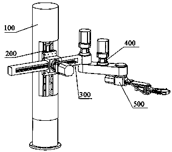
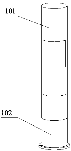
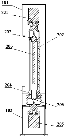
[0019] Such as figure 1 , figure 2 , image 3 , Figure 4 , Figure 5 , Figure 6 , Figure 7 As shown, the bearing ring forging clamps the manipulator, the fixed base 102 is fixed on the ground by bolts, the column 207 is fixed on the fixed base 102 by bolts, the column rotating motor 205 is fixed on the bottom of the fixed base 102 by bolts, and the two ends of the column drive shaft 206 are Connect with column rotating motor 205 and column 207 respectively, make column rotating motor 205 drive column 207 to rotate, lead screw motor 201 is fixed on the top of column 207 by bolt, screw lever 203 is fixed by column top cover 1 202, slide guide rail 208 is fixed on column 207 outside the open slot, the slider base 209 is installed on the sliding guide rail 208, slides up and down through the lead screw, the gear motor fixing base 210 is welded on the slider base 209, and the rack arm 301 passes through the gear motor fixing base 210, the gear motor 303 is fixed on the ge...


PUM


Abstract

The invention belongs to automatic equipment in the field of casting and forging, and relates to a device for forging a blank forge piece in a forging process of a bearing ring. A mechanical arm is characterized in that a base module plays a role in fixing and supporting the whole device, a vertical column movement module realizes the position rotation of the whole device in a horizontal plane andthe upper and lower displacement in the vertical direction, a large arm movement module realizes stretching of a large arm in the horizontal direction through a rack inside the large arm and is usedfor adjusting the grabbing radius of a mechanical claw, the working rotation radius is further improved through a small arm in a synchronous transmission module, a motor is arranged closer to a standcolumn through synchronous transmission, so that the motion balance is greatly improved, a mechanical arm module is a final implementation mechanism for realizing grabbing, through a rotary motor connected with the tail end, rotation by 180 degrees can be realized in the horizontal plane, so that the front and back surfaces of a clamped forge piece are fully forged.

Description

technical field [0001] The invention belongs to an automatic equipment in the field of casting and forging, and relates to a device for grabbing blank forgings for forging during the bearing ring forging process, and specifically relates to a device that can drive a screw slider and a rack and pinion to move by means of a motor to realize mechanical A kind of bearing ring forging synchronous transmission supporting manipulator for grabbing forgings by arm movement. Background technique [0002] Manipulator refers to an automatic device that imitates the movement mechanism of human hands and arms and can complete preset grasping, handling or some fixed operation steps. Strong adaptability, its application scope has become more and more extensive in recent years. In the bearing ring forging industry, in the face of harsh working environment, high-strength working methods, and worker safety, the role of manipulators is irreplaceable. At present, most of the mainstream manipula...

Claims


Application Information

Patent Timeline
IPC IPC(8): B21J13/10B21K1/04B21K27/00
CPCB21J13/10B21K1/04B21K27/00
Inventor 郭忠峰张渊博秦志超杨林
Owner SHENYANG POLYTECHNIC UNIV
Learn More