Crank-slider mechanism, parts and equipment

A technology of crank round slider and round slider, which is used in mechanical equipment, variable displacement engines, machines/engines, etc., to improve stiffness and strength, improve motion balance, and complete motion balance.

Active Publication Date: 2014-02-12
BEIJING SINOCEP ENGINE TECH
View PDF5 Cites 0 Cited by
  • Summary
  • Abstract
  • Description
  • Claims
  • Application Information

AI Technical Summary

Problems solved by technology

[0005]Especially when using a single-cylinder engine structure, the designer’s main consideration is that the structure of the single-cylinder engine is relatively simple and lightweight. If the dynamic balance slider is used as the dynamic balance component, If it is necessary to add a reciprocating mechanism, this reciprocating-rotary motion conversion mechanism is difficult to be called a single-cylinder machine structure, and the simple and light advantages of the single-cylinder machine are completely lost.

Method used


Image

  • Crank-slider mechanism, parts and equipment
  • Crank-slider mechanism, parts and equipment
  • Crank-slider mechanism, parts and equipment

Examples


Embodiment Construction

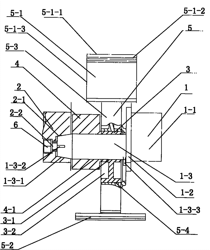
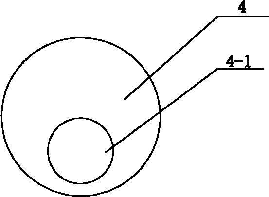
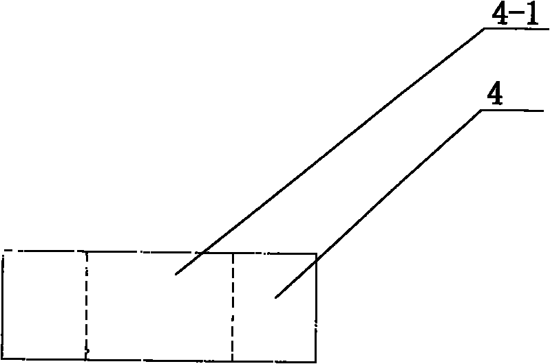
[0026] figure 1 It is a schematic structural diagram of the motion mechanism part of a crank-slider reciprocating piston internal combustion engine provided by the first embodiment of the present invention, that is, the crank-slider mechanism. It can be seen from this figure that the main moving parts of the crank circular slider mechanism inside the internal combustion engine and their interrelationships. In order to illustrate some specific parts, some positions in this figure are partially cut. Please see also figure 2 and image 3 , figure 2 Shows the front view of the dynamic balance block used in this mechanism; image 3 A top view of the dynamic balancing swivel is shown.

[0027] The internal combustion engine is a two-stroke diesel engine with a differential piston, which is reflected in figure 1 In the shown kinematic mechanism, it can be seen that the piston 5 is a double-acting piston with two piston heads having different diameters. The following combina...


PUM


Abstract

The invention provides a crank circular slider mechanism which comprises a crankshaft having at least one crank pin (1-3); at least one circular slider (3) with an eccentric hole (3-1) which fits over the crank pin (1-3) of the crankshaft; at least one reciprocating element (5) with circular slider -receiving hole (5-4), which receives the circular slider (3) in a rotatable manner, the amount of the element is equal to that of the circular slider; and at least one dynamic balance rotary block with an eccentric hole (4-1) which fits over the same one crank pin (1-3) of the crankshaft" the dynamic balance rotary block and the adjacent circular slider (3) are fixed together. By means of proper selection of mounting place and mass of the dynamic balance rotary block the mechanism can convert the reciprocating inertia of the reciprocating element into the rotation inertia so as to obtain the balance effect. The invention also provides a part for the crank circular slider mechanism and an internal combustion engine and compressor using the crank circular slider mechanisn.

Description

technical field [0001] The invention relates to a reciprocating-rotational mutual conversion mechanism, in particular to a crank circular slider mechanism. The invention also provides equipment using the crank-circular-slider mechanism. [0002] Background technique [0003] Both reciprocating internal combustion engines and compressors need to realize the conversion between the reciprocating motion of the piston and the rotational motion of the crankshaft. Among them, the reciprocating internal combustion engine converts the reciprocating motion of the piston into the rotational motion of the crankshaft, while the reciprocating compressor converts the reciprocating motion of the crankshaft. The rotary motion of the piston is converted into the reciprocating motion of the piston. Under the current common technology, the above-mentioned conversion process all needs to use the crank-link mechanism. Due to the presence of the connecting rods in the crank-and-link mechanism, t...

Claims


Application Information

Patent Timeline
Patent Type & Authority Patents(China)
IPC IPC(8): F16H21/18F16F15/28F04B39/00F02B75/32
CPCF04B53/006F16F15/283F16H21/36F04B39/0094F01B9/06F02B75/32F04B9/045F04B27/053Y10T74/18208F16H21/22
Inventor 黎明黎正中
Owner BEIJING SINOCEP ENGINE TECH
Why Eureka
Try Eureka