Method and apparatus for frame detection in a communications system

A kind of equipment and technology to be tested, applied in the direction of multiplexing communication, time division multiplexing system, wireless communication, etc., can solve the problem of not receiving the filtering and decoding circuit system correctly

Active Publication Date: 2011-06-01
LGC WIRELESS
View PDF11 Cites 19 Cited by
  • Summary
  • Abstract
  • Description
  • Claims
  • Application Information

AI Technical Summary

Problems solved by technology

In some systems, the network device does not have the circuitry needed to properly receive, filter, and

Method used


Image

  • Method and apparatus for frame detection in a communications system
  • Method and apparatus for frame detection in a communications system
  • Method and apparatus for frame detection in a communications system

Examples


Embodiment Construction

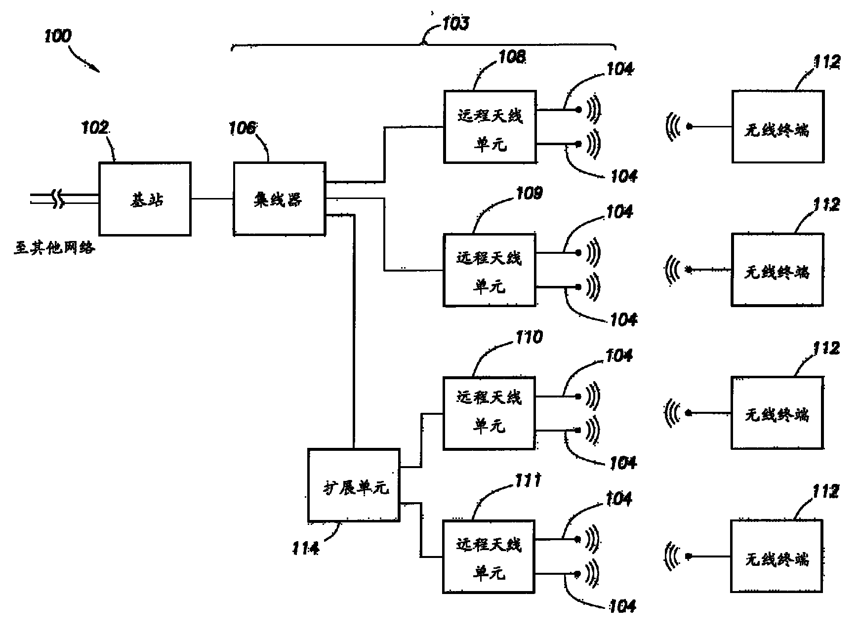
[0012] figure 1 is a block diagram of one embodiment of a communication network 100 . exist figure 1 In the illustrated embodiment, the communication network 100 includes a base station 102 communicatively coupled with a distributed antenna system (DAS) 103 . In other embodiments, DAS 103 is used to communicate between one or more upstream devices (e.g., base transceiver station 102, wireless access point, or other radio frequency signal source) and one or more downstream wireless devices (e.g., wireless terminal 112 ) to transmit radio frequency signals. In some embodiments, base station receiver 102 (also referred to herein as "base station" 102) is part of a telecommunications service provider's infrastructure, and wireless terminal 112 comprises customer premises equipment. Generally, for each radio frequency signal or channel on which base station 102 communicates with downstream wireless terminals 112, a raw downlink radio frequency signal is initially transmitted by ...


PUM


Abstract

A method of determining a boundary of a subframe in a time division duplexing (TDD) system is provided. The method detects a power level of a signal on at least one radio frequency, the signal comprising at least one subframe. A time-domain correlation is done on the detected signal with a first reference signal, wherein the first reference signal represents at least one subframe. The location in time of a boundary of the at least one subframe of the detected signal is determined based on the correlation of the detected signal and the first reference signal.

Description

[0001] Cross References to Related Applications [0002] This application is related to the following applications, filed on the same date, which are hereby incorporated by reference: U.S. Patent Application No. 12 / 144,977, entitled "METHOD AND APPARATUS FOR SWITCHING IN A TDD SYSTEM," Attorney Docket No. 100.916US01 ; U.S. Patent Application No. 12 / 144,939, entitled "SYSTEM AND METHOD FOR SYNCHRONIZED TIME-DIVISION DUPLEX SIGNAL SWITCHING," Attorney Docket No. 100.924US01; and "SYSTEM AND METHOD FOR CONFIGURABLE TIME-DIVISION DUPLEX INTERFACE" , US Patent Application No. 12 / 144,913, Attorney Docket No. 100.925US01. Background technique [0003] Communication equipment in a Time Division Duplex (TDD) system must be coordinated to switch between uplink and downlink communications at the appropriate time for the TDD system to function properly. Typically, the host unit coordinates the number of handovers and the host unit sends information about the number of handovers to the w...

Claims


Application Information

Patent Timeline
IPC IPC(8): H04J3/02H04B7/212H04B7/26
CPCH04L5/1469H04L27/2656H04J3/0608H04W56/008
Inventor S.斯特拉特福德D.武契奇
Owner LGC WIRELESS
Why Eureka
Try Eureka