Fishing lamp

A fish-spotting light and light distribution control technology, which is applied in the field of fish-spotting lights, can solve problems such as re-leaving of catches, changes in illuminance distribution in the sea, and difficulty in gathering catches, etc., so as to reduce the change of relative intensity and improve the ability of gathering fish Effect

Active Publication Date: 2011-06-08
NICHIA CORP +1
View PDF8 Cites 3 Cited by
  • Summary
  • Abstract
  • Description
  • Claims
  • Application Information

AI Technical Summary

Problems solved by technology

[0009] That is, conventional fish gathering lights have problems in that the distribution of illuminance in the sea changes due to the shaking of the ship, making it difficult for cuttlefish, saury, sardines, and trevally to gather, or the gathered catches leave again.

Method used


Image

  • Fishing lamp
  • Fishing lamp
  • Fishing lamp

Examples


Embodiment Construction

[0041] Hereinafter, an embodiment for implementing the present invention will be described with reference to the drawings. However, the aspects shown below are merely examples for actualizing the technical idea of ​​the present invention, and the following contents do not limit the present invention.

[0042] (Embodiment 1)

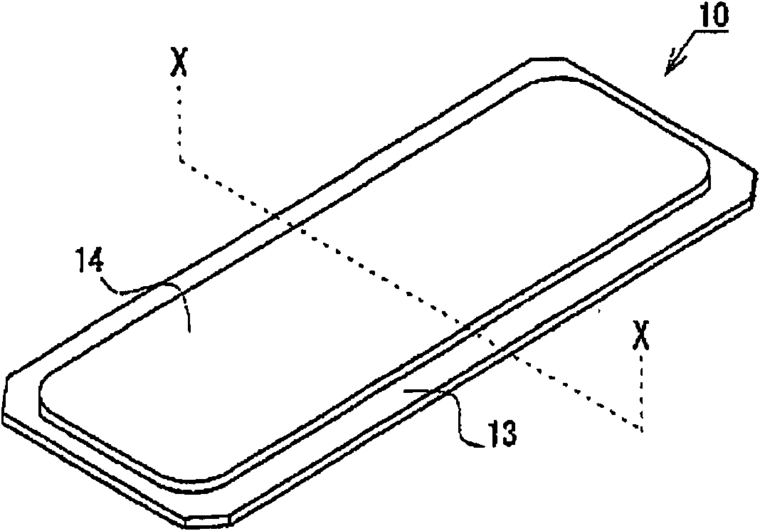
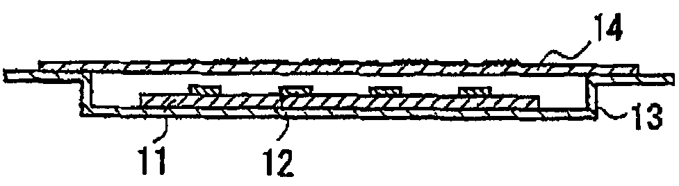
[0043] Fig. 1 shows a fish-spotting light 10 of this embodiment. Fig. 1(a) is a perspective view, and Fig. 1(b) is an X-X sectional view of a cross-sectional view of Fig. 1(a). The fish-spotting light 10 includes a substrate 11 , LEDs 12 arranged on the substrate 11 as light sources, a housing 13 housing the substrate 11 , and a light distribution control member 14 that controls light distribution of light from the LEDs 12 . The light distribution control member 14 is fixed to the frame body 13 with screws or the like, but is not particularly shown here.

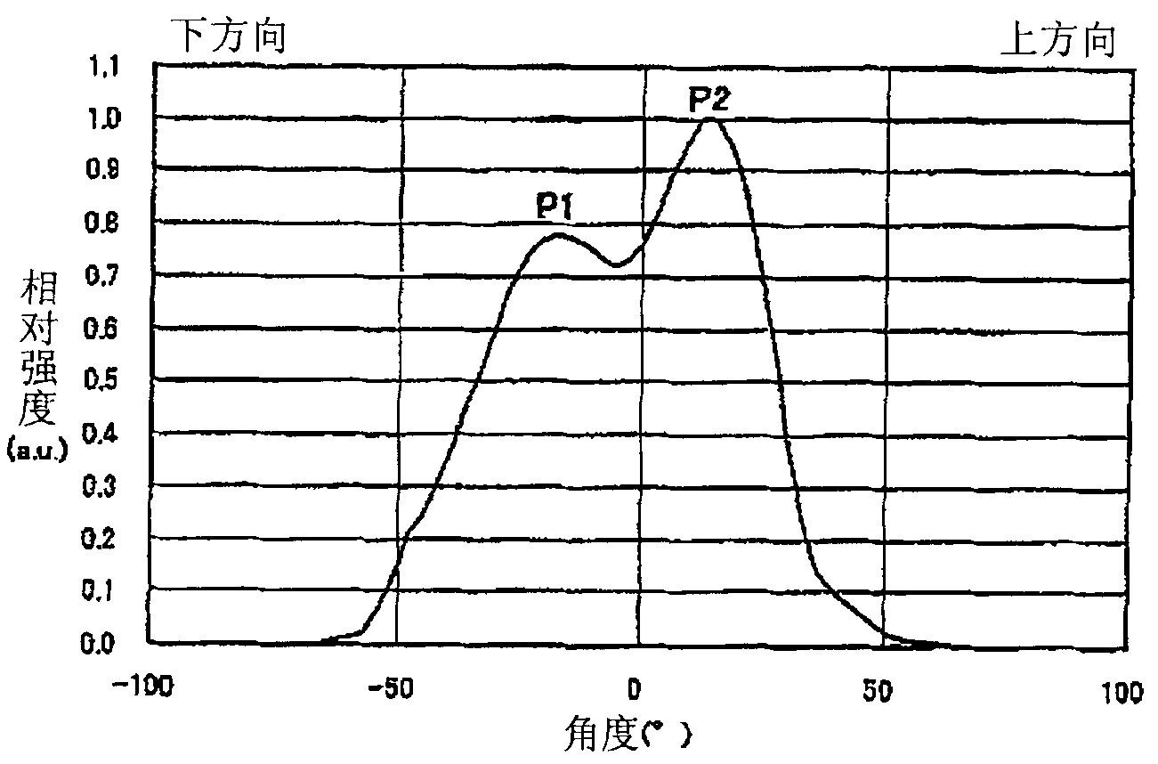
[0044] figure 2 Represent the light distribution pattern (the left and right direction of Fig. 1...


PUM


Abstract

Conventional fishing lamp has the problems that variation of illumination intensity due to shaking of a boat may result in that inkfish, pacific sauries, sardines and barracuda are unlikely to gather or likely to depart again after gathering. The fishing lamp 10 is characterized in comprising a section including a grading mode having a first grading peak P1 and a second grading peak P2 different from each other, and the first grading peak P1 is smaller than the second grading peak P2.

Description

technical field [0001] The invention relates to a fish gathering lamp for gathering cuttlefish, saury, sardines, trevally and the like. Background technique [0002] In the past, the polyfish lamps that used incandescent lamps, halogen lamps, metal halide lamps, etc. had the following problems: a large amount of fuel was consumed due to poor light utilization efficiency, and a large amount of CO was emitted. 2 and increase the burden on the environment. In addition, there is a problem that excessively dazzling light irradiated in all directions, which can be confirmed from artificial satellites, becomes light pollution, and light including ultraviolet rays has a bad influence on the human body. Under such circumstances, a fish-spotting light using LED (light-emitting diode, light-emitting diode) as a light source has been proposed in recent years. [0003] For example, the following content is described in Patent Document 1: use two LED planar light sources to combine a ri...

Claims


Application Information

Patent Timeline
Patent Type & Authority Applications(China)
IPC IPC(8): A01K79/00F21V5/04F21Y101/02F21Y115/10
Inventor 加藤胜渡边和宪稻田博史
Owner NICHIA CORP
Why Eureka
Try Eureka