Method for detecting leaking point position of buried pipeline by gas

A buried pipeline, gas detection technology, applied in pipeline systems, gas/liquid distribution and storage, mechanical equipment, etc., can solve the problems of gas leakage, unable to detect the location of water leakage points, etc., to reduce the time for leak detection. Effect

Inactive Publication Date: 2011-06-08
广东精测勘测科技股份有限公司
View PDF3 Cites 26 Cited by
  • Summary
  • Abstract
  • Description
  • Claims
  • Application Information

AI Technical Summary

Problems solved by technology

[0014] The main purpose of the present invention is to provide a method of using gas to detect the location of the leak point of buried pipelines. By artificially injecting gas with a light relative molecular weight into the pipeline suspected of having a leak, the gas will leak out through the leak, and then Float to the surface, use the corresponding gas detector on the surface to detect the concentration of the gas, so as to determine where the buried pipeline is damaged or leaked, and solve the problem of trachoma leakage and leakage in the current use of non-metallic material pipelines After waiting for a small leak, the conventional sonic leak detection method cannot detect the location of the leak point

Method used


Image

  • Method for detecting leaking point position of buried pipeline by gas
  • Method for detecting leaking point position of buried pipeline by gas
  • Method for detecting leaking point position of buried pipeline by gas

Examples


Embodiment Construction

[0032] A method of using gas to detect the location of a leak point of a buried pipeline, comprising the following steps:

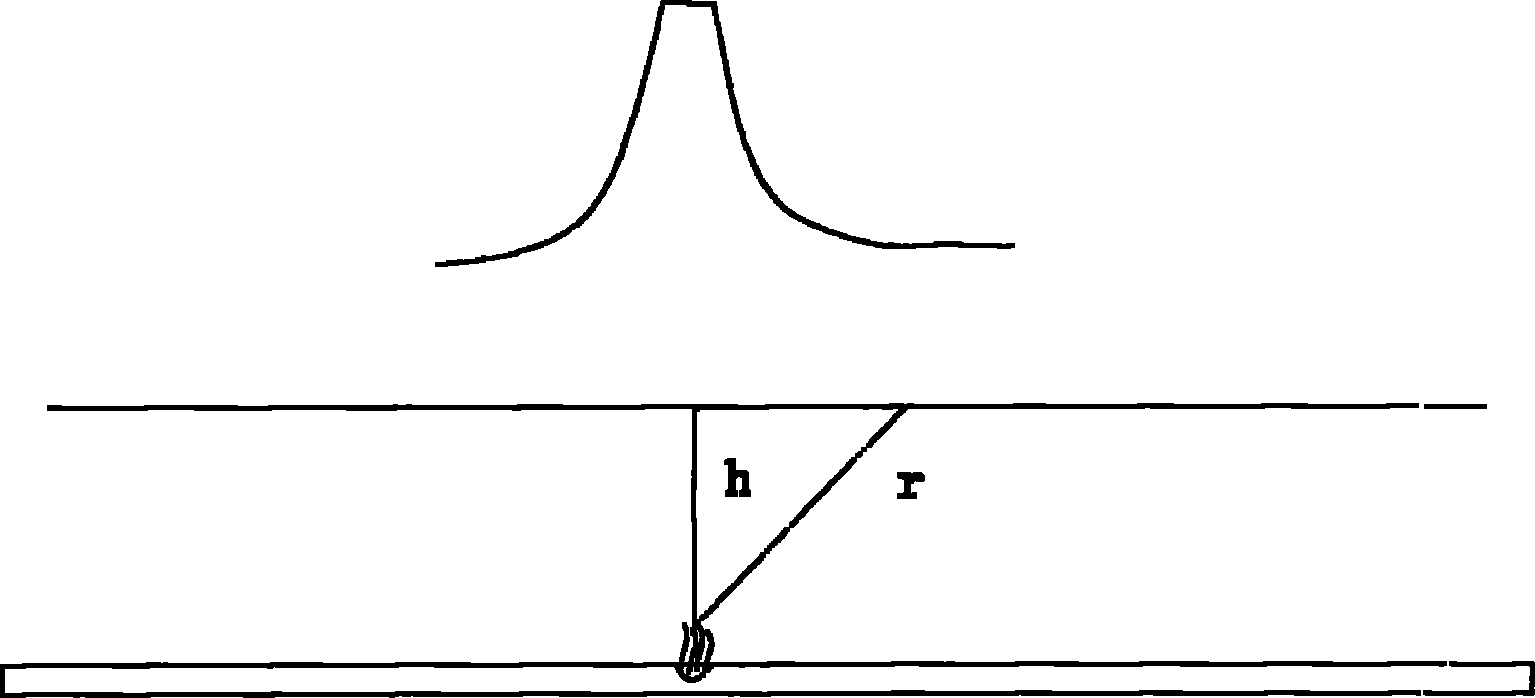
[0033] first step, such as image 3 As shown, the tracer gas E is injected into the buried pipeline F, so that the tracer gas E is distributed in the buried pipeline F, and the pressure inside the buried pipeline F is higher than atmospheric pressure.

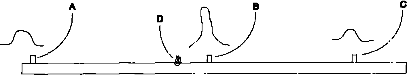
[0034] In the second step, several equidistant detection holes H are opened on the ground directly above the buried pipeline F, and gas detectors matching the tracer gas E are placed in the several detection holes H.

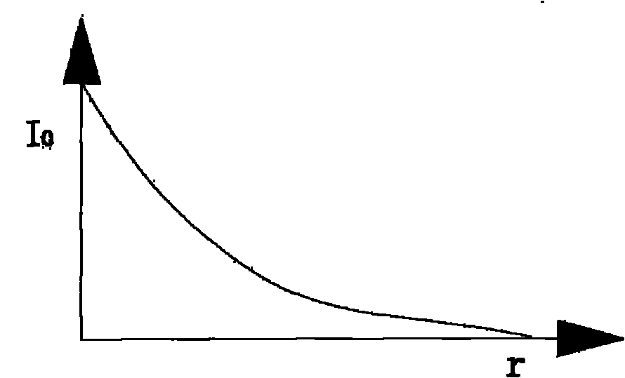
[0035] If there is a leak point G in the buried pipeline F, the tracer gas E leaks out of the buried pipeline F and penetrates directly above the buried pipeline F. At this time, the gas located above the leak point G The detector detects the tracer gas leaked from the buried pipeline F, thereby determining the position of the leak point G; if the gas detector located above the buried pipel...


PUM


Abstract

The invention provides a method for detecting a leaking point position of a buried pipeline by gas. In the method, gas with light relative molecular mass is artificially introduced into a pipeline which is suspected to be leaked, and gas can escape from a leaking port and flows above the surface; a corresponding gas detector is used on the surface to detect the concentration of gas, so that damage, leakage and the like on the position of the buried pipeline can be judged to solve the problem that the position of a water leaking point cannot be detected by the conventional sound wave method in leak detection after the current non-metal material pipeline has sand hole leakage, seepage and other small leaking conditions in the using process. Furthermore, the specific position of any leaking point of any buried pipeline can be detected by the method, and the leaking position is positioned accurately in +/-1m. The method can greatly reduce the time for finding the leaking point and reduce the dig area which the leaking point is repaired.

Description

technical field [0001] The invention relates to a pipeline detection method, more specifically a method for detecting the position of a buried pipeline leakage point by using gas. Background technique [0002] In modern urban life, the "running, leaking, dripping, and leaking" of tap water is a long-term problem faced by urban water supply companies, property communities, and large enterprises, institutions, and factories. The waste of water is not only a waste of precious natural resources, but also causes great direct economic losses and burdens to urban water companies, property communities, enterprises and institutions. Leakage of fire hoses is a great safety hazard. Therefore, the use of leak detection equipment with accurate positioning and correct detection methods is very much needed by various enterprises. [0003] The method of existing underground water pipe leak detection mainly is: acoustic wave method. The instruments used are: listening rods, electronic lea...

Claims


Application Information

Patent Timeline
Patent Type & Authority Applications(China)
IPC IPC(8): F17D5/02
Inventor 赵子云
Owner 广东精测勘测科技股份有限公司
Why Eureka
Try Eureka