Check patentability & draft patents in minutes with Patsnap Eureka AI!

3D (three-dimensional) mechanical probe

A mechanical and 3D technology, applied in the field of probe transmission system, can solve the problems of difficult installation of ropes and difficulty in adjusting the tightness of ropes.

Active Publication Date: 2011-06-08
SHENZHEN MINDRAY BIO MEDICAL ELECTRONICS CO LTD +1
View PDF4 Cites 11 Cited by
  • Summary
  • Abstract
  • Description
  • Claims
  • Application Information

AI Technical Summary

Problems solved by technology

Therefore, the tightness of the rope is difficult to adjust, and the rope is difficult to install

Method used


Image

  • 3D (three-dimensional) mechanical probe
  • 3D (three-dimensional) mechanical probe
  • 3D (three-dimensional) mechanical probe

Examples


Embodiment 1

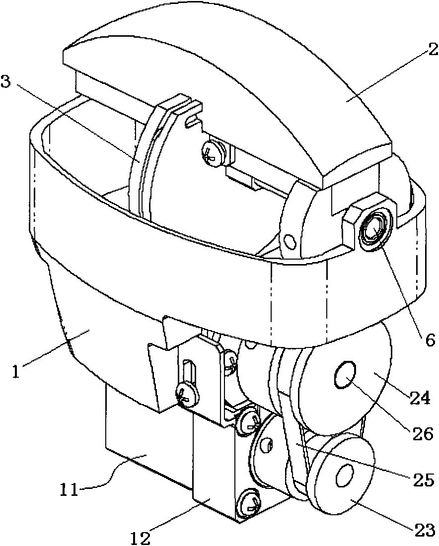
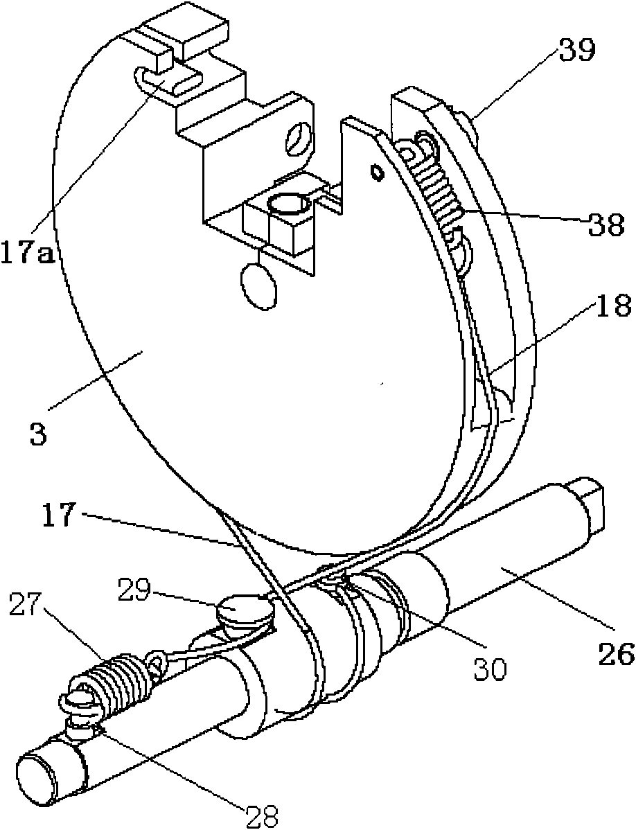
[0019] The 3D mechanical probe of Embodiment 1 includes: a base 1, an acoustic head 2, a driven wheel 3 with a hole, a motor 11, a transmission system, a rope adjustment pin 41 and a first rope 17, and the motor 11 is fixedly connected to the base 1 And drive the transmission system to move, the transmission system connects the first rope 17 and drives the first rope 17 to move, the first rope 17 drives the passive wheel 3 to move, the passive wheel 3 is connected with the sound head 2 and drives the sound head to swing, the rope adjustment pin 41 is inserted In the hole of the passive wheel 3, one end of the first rope 17 is wound on the rope adjustment pin 41, and the length of the rope wound on the rope adjustment pin 41 can be adjusted by rotating the rope adjustment pin 41, thereby changing the first rope that drives the driven wheel to rotate. The effective length of 17, the effective length here refers to the length that actually works when the rope drives the driven whe...

Embodiment 2

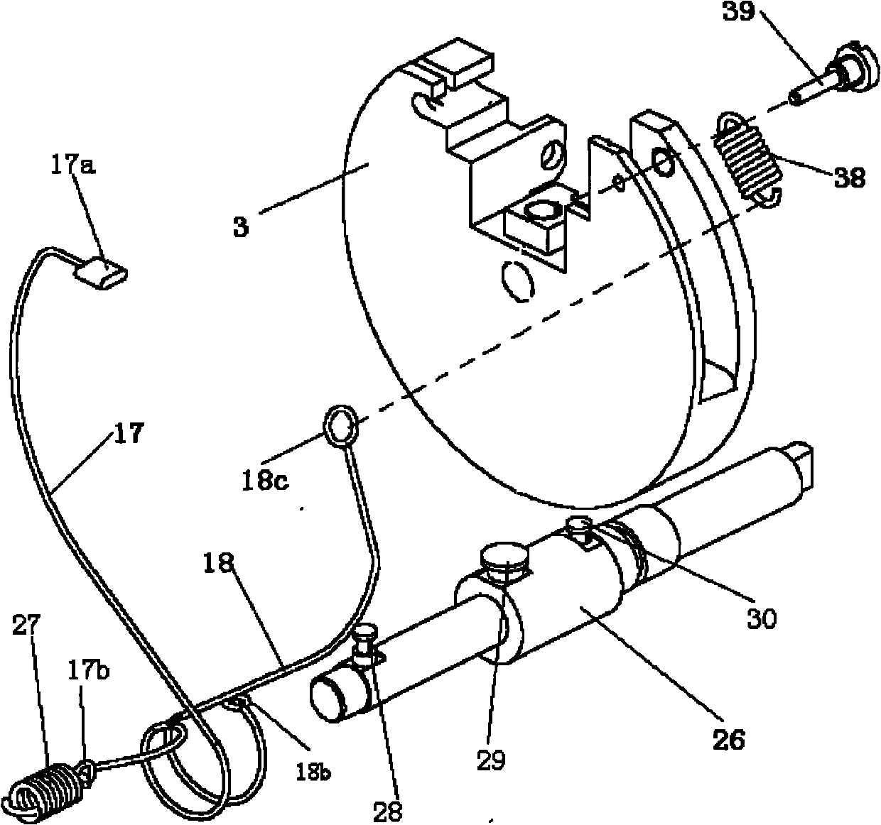
[0022] The difference between the second embodiment and the first embodiment is that another connection mode between the first rope 17 and the rope adjustment pin 41 is as follows: Figure 8As shown, the rope adjustment pin 41 is designed with a through hole 41c. Before the installation of the first rope 17, the knot 17a cannot be processed. When the first rope 17 is installed, the rope adjustment pin 41 can be inserted in the holes 3a and 3b of the driven wheel 3 earlier. The first rope 17 passes through the through hole 41c without the knot 17a, and then the first rope 17a passes through the hole 41c. The end processing a knot 17a. The knot can be processed by riveting, that is, first put a metal sleeve on the end of the rope, and then flatten the metal sleeve. In this connection mode, the knot 17a can only be processed after the first rope 17 passes through the through hole 41c on the rope adjusting pin 41, so the installation is slightly complicated, but the structure is...


PUM


Abstract

The invention discloses a 3D (three-dimensional) mechanical probe. The probe comprises a substrate, a sound head, a driven wheel, a motor, a transmission system, a first rope and a rope adjusting pin, wherein the sound head transmits an ultrasonic signal; a hole is formed on the driven wheel, the driven wheel is fixedly connected with the sound head to drive the sound head to swing; the motor is fixedly connected with the substrate; the transmission system is connected with the motor and the first rope respectively, the power output of the motor drives the transmission system to move, and the transmission system drives the first rope to move; one end of the first rope is connected with the transmission system, and the other end of the first rope is wound on the rope adjusting pin; and the rope adjusting pin is inserted in the hole of the drive wheel and can rotate in the hole. In the technical scheme, the rope adjusting pin can be used for adjusting the effective length of the rope, and the actual acting length of the rope can be adjusted by rotating the adjusting pin, so the rope is prevented from loosing or over tightening in the working process.

Description

technical field [0001] The invention relates to an ultrasonic probe, in particular to a transmission system of the probe. Background technique [0002] Generally, the ultrasonic probe with 3D imaging function is called 3D mechanical probe, and there is generally a stepping motor as a driving power source inside it, and the stepping motor drives the sound head to swing within a certain angle through the transmission system under signal control. [0003] The transmission system can be realized in the following ways: such as Figure 1-3 As shown, the motor 11 is fixed on the base 1 through the motor support 12, and the output shaft of the motor 11 is fixedly connected with the active synchronous pulley 23, and the active synchronous pulley 23 transmits the motion output of the motor 11 to the passive one through the synchronous belt 25. The synchronous pulley 24 and the passive synchronous pulley 24 are fixedly connected to the driving shaft 26, and the driving shaft 26 is supp...

Claims


Application Information

Patent Timeline
Patent Type & Authority Applications(China)
IPC IPC(8): G01D11/00
CPCG01S15/894G10K11/355A61B8/4461A61B8/4494A61B8/4466G01S7/52079G01S15/8993
Inventor 唐生利
Owner SHENZHEN MINDRAY BIO MEDICAL ELECTRONICS CO LTD
Features
  • R&D
  • Intellectual Property
  • Life Sciences
  • Materials
  • Tech Scout
  • Unparalleled Data Quality
  • Higher Quality Content
  • 60% Fewer Hallucinations
Learn More