
Process for producing composite molding

A manufacturing method and compound forming technology, applied in the direction of coating, etc., can solve the problems of impracticality, good composite formed products, and inability to form, and achieve the effects of excellent tightness, simple temperature control, and short forming cycle

Inactive Publication Date: 2011-06-08
POLYPLASTICS CO LTD
View PDF8 Cites 1 Cited by
  • Summary
  • Abstract
  • Description
  • Claims
  • Application Information

AI Technical Summary

Problems solved by technology

However, this method requires strict control of temperature and pressure, and there is a tendency to increase auxiliary equipment, so it cannot be said to be practical.
In addition, in Japanese Patent Application Laid-Open No. 2001-1382, it is assumed that low-density polyethylene resin, polypropylene, polystyrene, etc. are polyarylene sulfide resins and polyamide resins. The method of the No. 1382 bulletin cannot obtain a composite molded product with good adhesion between resin and metal
[0005] On the other hand, in Japanese Patent Laid-Open No. 2005-342922, it is proposed to use a mold with a surface treatment using a diamond carbon film to improve the tight bonding strength between metal and resin. However, in this solution, there is The problem that molding cannot be performed with a practical molding cycle time

Method used


Image

  • Process for producing composite molding
  • Process for producing composite molding
  • Process for producing composite molding

Examples


Embodiment 1

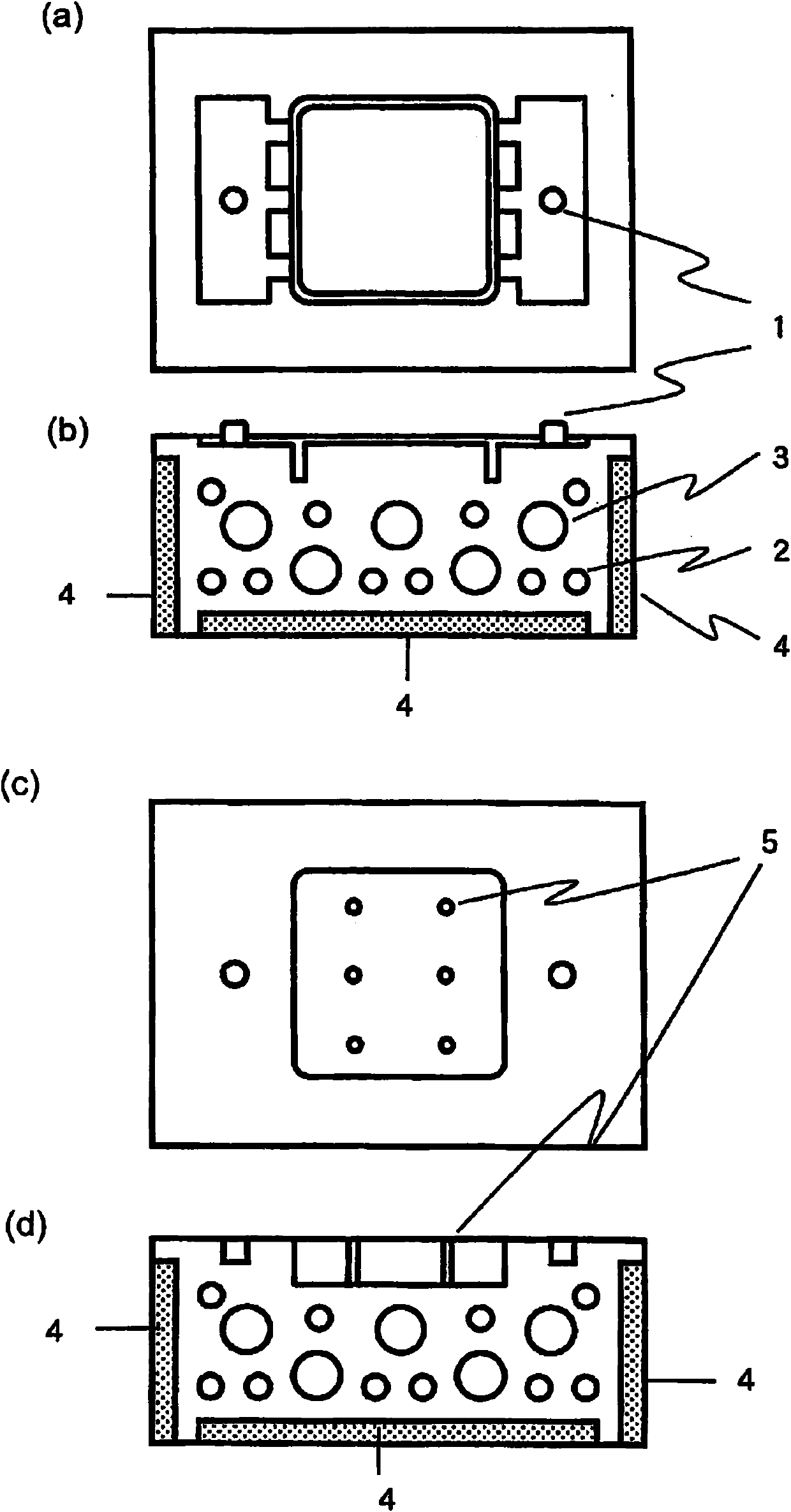
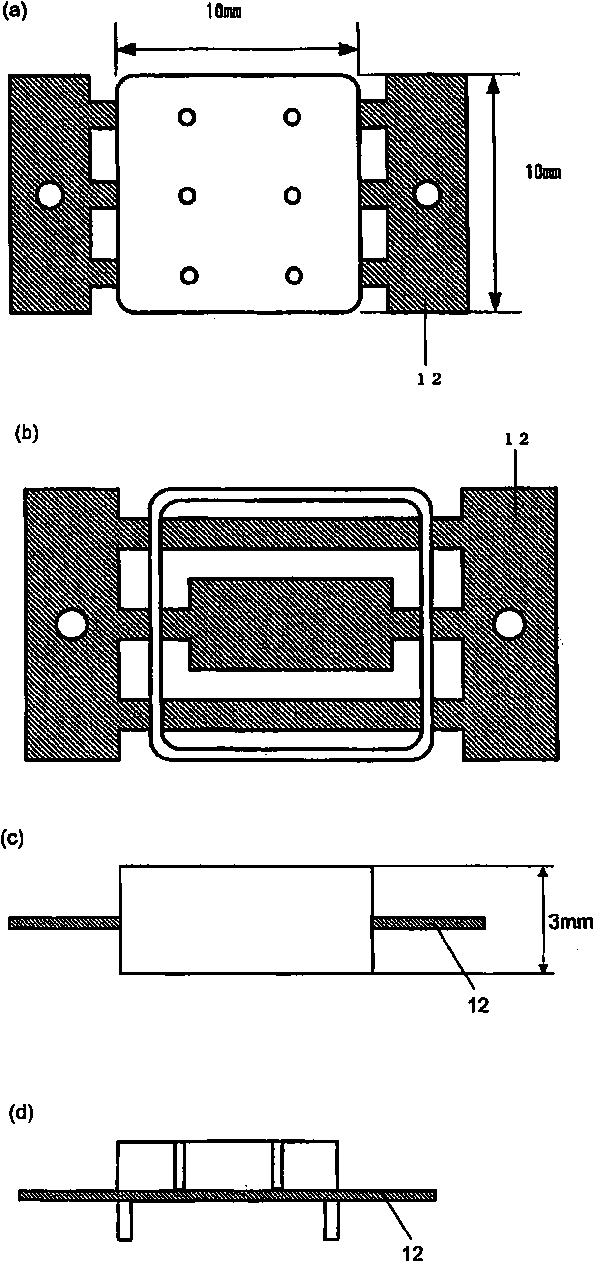
[0087] used by embedding with figure 1 Shown is a molding mold composed of a main mold of a core mold with a heating circuit and a cooling circuit. The main mold is used to control the linkage with the molding equipment. The temperature of the main mold is kept at 150°C. figure 2 Immediately after the metal parts shown were arranged in the mandrel, the temperature of the mandrel was raised from 150°C to a predetermined temperature (245°C), and it took 9.5 seconds to reach 245°C. Meanwhile, after closing the mold for molding, by injection molding the PPS resin under the following conditions, the following image 3 Such composite molded products.

[0088] Material 1 in Table 1 was used as the PPS resin.

[0089] Forming conditions

[0090] Surface treatment of the mandrel: Surface coating treatment was carried out on the steel material SUS420J2, and a diamond carbon film (DLC) with a thickness of 1.0 μm was applied. The surface roughness was as follows: the ten-point aver...

Embodiment 2

[0107] Molding and evaluation were performed in the same manner as in Example 1 except that Material 2 in Table 1 was used as the PPS resin.

Embodiment 3

[0109] Molding and evaluation were performed in the same manner as in Example 1 except that the core mold temperature during injection molding was 200°C.


PUM

PropertyMeasurementUnit
mean roughnessaaaaaaaaaa
surface roughnessaaaaaaaaaa

Abstract

A process for producing a composite molding comprising one or more thermoplastic resins selected between a polyarylene sulfide resin and a polyamide resin and a metallic part and stably having satisfactory adhesion. A reduction in molding cycle time can be attained in the process. The process is characterized in that (1) a mold is used which is divided into a main mold for controlling linkage with a molding machine and a core which has a circuit for heating and a circuit for cooling and involves inside an area where the one or more resins come into contact with a metallic part. The process is further characterized in that (2) that part of the mold which comes into contact with the resin(s) flowing in during molding has been surface-treated so as to have a ten-point average roughness (Rz) of 0.5 [mu]m or less, and the core has a capacity of 60 cm3 or less and has been embedded in the main mold, with that peripheral part of the core which is in contact with the main mold having been heat-insulated. The process is furthermore characterized by (3) setting the metallic part in the mold, heating the core to a temperature in a specific range, injecting the resin(s) to fill the cavity therewith while keeping that temperature of the core, and immediately after completion of the filling of the mold cavity with the resin(s), blocking the heating circuit of the core and rapidly cooling the core with the cooling circuit of the core at a cooling rate of 7 DEG C / sec or higher.

Description

technical field [0001] The present invention relates to a method for producing a composite molded product of one or more thermoplastic resins selected from polyarylene sulfide resins and polyamide resins and metal parts, and specifically relates to ensuring excellent adhesion between resin and metal parts A method of manufacturing a composite molded product that combines properties and improves the molding cycle. Background technique [0002] Composite molded products composed of resin and metal represented by insert molded products are used in the manufacture of electrical and electronic parts, automobile parts, etc. However, the interface between the metal insert and the resin cannot be sufficiently tightly bonded by the usual molding method, which causes detachment and leakage of gas and liquid from the interface. In order to improve such disadvantages, there is known a method of surface-treating metal to form irregularities, and injecting molten resin into the irregular...

Claims


Application Information

Patent Timeline
Patent Type & Authority Applications(China)
IPC IPC(8): B29K105/22B29C45/14B29C45/73B29C33/38
CPCB29C45/14311B29C45/14778B29C45/72B29K2705/00B29C45/78
Inventor 宫本康满望月章弘金塚竜也
Owner POLYPLASTICS CO LTD
Learn More