Film flash evaporation proportion difference type concentrator

A concentrator and poor specific gravity technology, applied in the field of concentrators, can solve the problems of large power consumption, easy foaming and overflow of liquid vapor, and high steam energy consumption of the concentrator, so as to achieve low power consumption, avoid foaming and overflow, and consume steam less effect

Active Publication Date: 2012-12-12
中国船舶重工集团公司第七〇三研究所
View PDF0 Cites 0 Cited by
  • Summary
  • Abstract
  • Description
  • Claims
  • Application Information

AI Technical Summary

Problems solved by technology

[0003] The purpose of the present invention is to provide a membrane flash evaporation specific gravity difference concentrator to solve the problems of high steam energy consumption in the current concentrator, easy destruction of heat-resistant components in the feed liquid, easy foaming and overflow of liquid vapor in the same room, and large power consumption. question

Method used


Image

  • Film flash evaporation proportion difference type concentrator
  • Film flash evaporation proportion difference type concentrator
  • Film flash evaporation proportion difference type concentrator

Examples


specific Embodiment approach 1

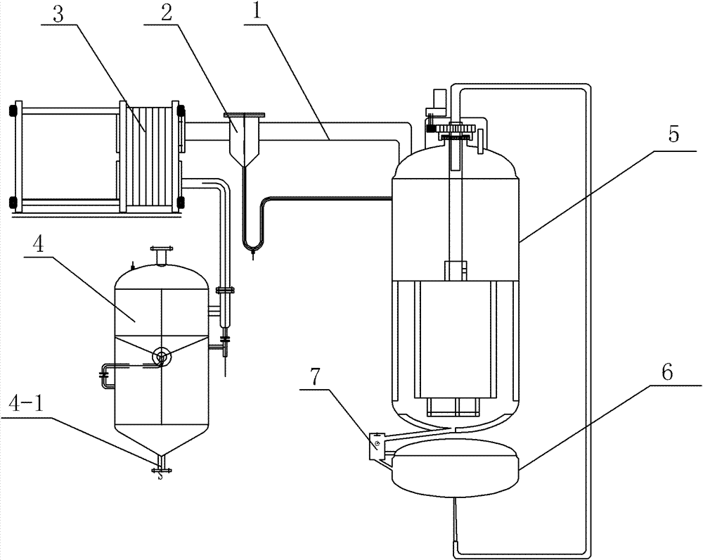
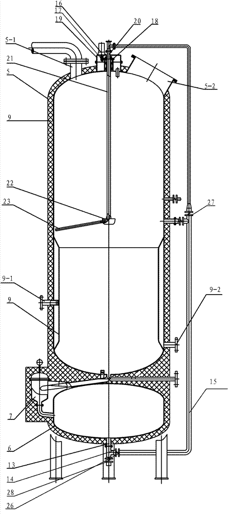
[0009] Specific implementation mode one: combine Figure 1-Figure 3 Description of this embodiment, the concentrator of this embodiment includes an evaporation tube 1, a vapor-liquid separator 2, a condenser 3 and a recovery liquid collector 4, and the bottom of the recovery liquid collector 4 is provided with a recovery liquid discharge port 4-1 , one end of the vapor collection pipe 1 communicates with the inlet of the vapor-liquid separator 2, the outlet of the vapor-liquid separator 2 communicates with the inlet of the condenser 3, and the outlet of the condenser 3 communicates with the inlet of the recovery liquid collector 4 The concentrator also includes a distribution device, an evaporation tank 5, a collection tank 6, a density measuring device 7, an outer jacket 9, a discharge pipe 13, a total feed pipe 14 and a first sub-feed pipe 15;

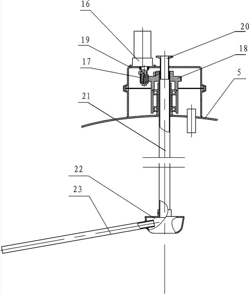
[0010] Described distributing device comprises motor 16, pinion gear 17, bull gear 18, sealing cover 19, the second sub-feeding pip...

specific Embodiment approach 2

[0012] Specific implementation mode two: combination figure 2 To illustrate this embodiment, the top of the evaporation tank 5 of this embodiment is provided with a quick-opening inlet 5-2, and this structure is used for fast feeding of feed liquid. Other components and connections are the same as those in the first embodiment.

specific Embodiment approach 3

[0013] Specific implementation mode three: combination figure 2 Describe this embodiment, the outer jacket 9 of this embodiment is provided with a first condensed gas outlet 9-2, and this structure is used for exhausting. Other components and connections are the same as those in the first embodiment.


PUM


Abstract

The invention relates to a film flash evaporation proportion difference type concentrator. The invention aims at the following problems of the current concentrators: the steam energy consumption is high; the non-heat-resistant components in the material liquid are easy to destroy; foaming over is easy to happen when the liquid and the steam are in the same chamber; and lots of power energy is consumed. The concentrator is characterized in that the bottom of a seal cover is fixedly connected with the outer wall of the upper seal head of an evaporating tank; the upper seal head of the evaporating tank is provided with a vacuuming port; the other end of an evaporating steam gathering tube is communicated with the vacuuming port; outer jackets are arranged inside the evaporating tank; the diameters of the top and bottom of the outer jackets are gradually expanded; the two ends of the outer jackets are fixedly connected with the inner walls of the evaporating tank; the lower seal head of the evaporating tank is communicated with the inlet end of a dasymeter; the outlet end of the dasymeter is communicated with a gathering tank; the bottom of the gathering tank is communicated with a general feed tube via a discharge tube; the general feed tube is communicated with one end of a first branch feed tube; the other end of the first branch feed tube is communicated with a second branch feed tube; and a first steam inlet is arranged on one outer jacket. The concentrator is used for concentrating the material liquid.

Description

technical field [0001] The present invention relates to a concentrator. Background technique [0002] The existing concentrators are divided into seven types: vacuum decompression concentrator, falling film evaporator, external circulation evaporator, double (three) effect falling film evaporator, double (three) effect external circulation evaporator, Forced circulation evaporator and scraper concentrator; the common shortcomings of the above concentrators except the scraper concentrator are: the influence of the static pressure head in the evaporator and the frictional resistance generated by the fluid flowing through the heating tube lead to a further increase in the boiling point of the solution, The consumption of steam energy is high; during the concentration process, the feed liquid is continuously heated during concentration, and the cycle heating time is long, and the heat-resistant components in the feed liquid are easily damaged; the temperature of the feed liquid ...

Claims


Application Information

Patent Timeline
Patent Type & Authority Patents(China)
IPC IPC(8): B01D1/22
Inventor 刘庆阁王建忠傅琳陈兴龙栾洋高斌唐晓彬王翠鸣赵旭
Owner 中国船舶重工集团公司第七〇三研究所
Why Eureka
Try Eureka