
Electric iron

A technology of electric soldering iron and soldering iron, applied in the direction of soldering iron, metal processing equipment, manufacturing tools, etc., can solve the problems of easy fatigue of fingers, inability to operate power wires, etc., and achieve the effect of flexible and convenient operation

Inactive Publication Date: 2011-06-15
吴明武
View PDF0 Cites 8 Cited by
  • Summary
  • Abstract
  • Description
  • Claims
  • Application Information

AI Technical Summary

Problems solved by technology

[0003] In summary, the purpose of the present invention is to solve many inconveniences such as the fatigue of the fingers when holding the traditional electric soldering iron, the inability to operate due to the narrow space during the welding process, and the influence of the swing of the power supply wire, and many other inconveniences.

Method used


Image

  • Electric iron
  • Electric iron
  • Electric iron

Examples


Embodiment Construction

[0022] Below in conjunction with accompanying drawing and preferred specific and embodiment, the structure of the present invention is described further:

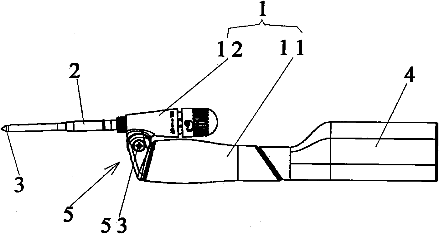
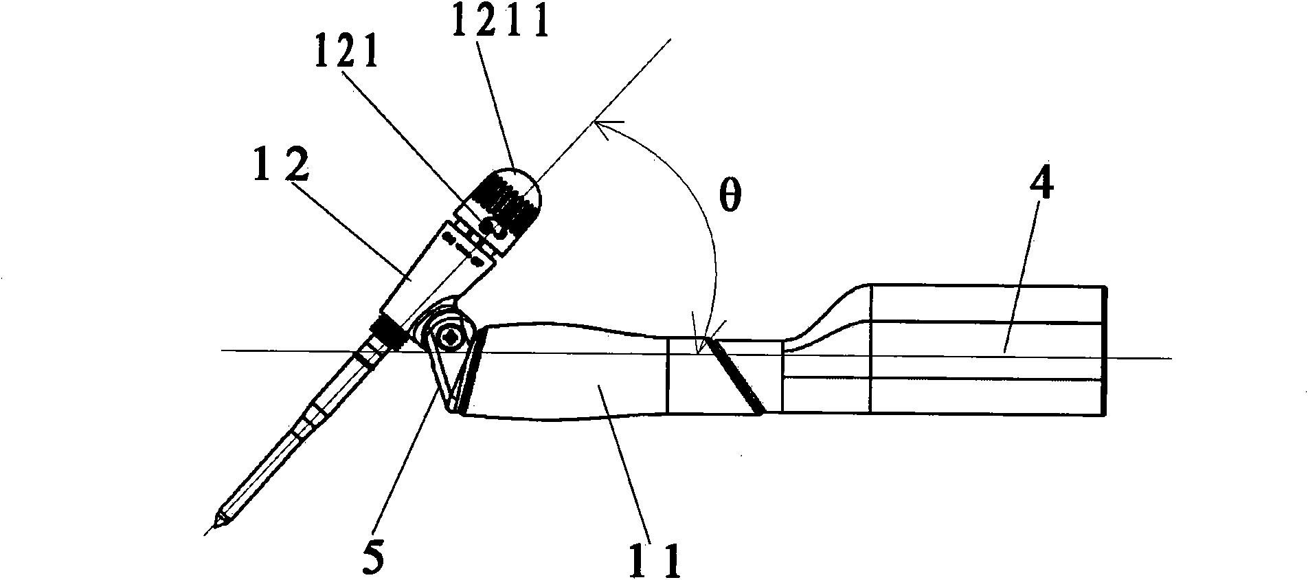
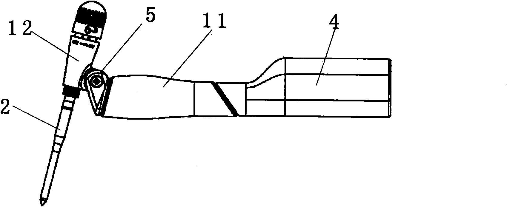
[0023] refer to figure 1 , figure 2 and image 3 As shown in , the present invention includes: a soldering iron handle 1 , a soldering iron rod 2 and a soldering iron tip 3 . The soldering iron handle 1 is composed of two parts, the handle body 11 and the handle head 12. The handle body 11 is the part held by the hand during operation. The shape of 11 is a streamline structure designed according to the principle of ergonomics; the handle 12 is in the shape of a circular platform, the soldering iron rod 2 and the handle 12 are on the same straight line, the front end of the soldering iron rod 2 is connected with the soldering iron tip 3, and the tail of the soldering iron rod 2 The end is connected on the front end of the crown 12, which is also the upper bottom surface of the round table. The rear end of the crown 12 is...


PUM


Abstract

The invention discloses an electric iron, which relates to the technical field of industrial electronic tools and solves the problem that hand fatigue is caused easily when the conventional electric iron is held by hand, the problem that operation cannot be performed in a welding process due to limitation of a narrow space, the problem that the swinging of a power wire affects the use of the electric iron, and other inconvenience problems. The invention adopts a technical scheme that: the electric iron comprises an iron handle, an iron rod and an iron head, wherein one end of the iron rod is connected with the iron handle, and the other end of the iron rod is connected with the iron head; and the electric iron is characterized in that: the iron handle comprises a handle body and a handle head, the front end of the handle body is connected with the side wall of the handle head through a hinge structure, and the iron rod is arranged on the top part of the front end of the handle head of the iron handle. The angles of the iron handle and the iron rod can be regulated according to the needs in operation, and the electric iron can be held by hand comfortably; and when the electric iron is operated in a narrow space, only the front end of the iron handle of the electric iron is put in the narrow space, the part of the rear end of the iron handle is kept outside the narrow space, and thus, multi-angle, multi-direction and flexible welding operation can be performed.

Description

technical field [0001] The invention relates to the technical field of industrial electronic tools, in particular to an aspect of the structure of an electric soldering iron for welding. Background technique [0002] At present, the soldering iron handle and the soldering iron rod of the electric soldering iron on the market are on the same straight line. During the soldering process, the posture of holding the electric soldering iron is similar to the posture of holding a pen when writing, that is, only relying on the cooperation of the middle finger, index finger and mother finger To clamp, the fingers are prone to fatigue and trembling after long-term operation, which affects the welding quality; when the traditional straight-line electric soldering iron is repairing the equipment in a narrow space, the electric soldering iron cannot fully enter the equipment for welding, especially When multi-angle soldering is blocked by equipment or components, it cannot be operated at...

Claims


Application Information

Patent Timeline
Patent Type & Authority Applications(China)
IPC IPC(8): B23K3/03
Inventor 吴明武
Owner 吴明武
Learn More