Rotary cutter

A technology of rotating knives and knives, applied in the field of rotating knives, to achieve the effect of saving internal space, compact structure and convenient use

Inactive Publication Date: 2011-06-15
广东金辉刀剪股份有限公司
View PDF0 Cites 2 Cited by
  • Summary
  • Abstract
  • Description
  • Claims
  • Application Information

AI Technical Summary

Problems solved by technology

[0004] The purpose of the present invention is to provide a rotary knife, which can solve the problem that the existing knife cannot be rotated relative to the knife handle and can be stretched, so as to be suitable for application in the field of packaging and other related occasions

Method used


Image

  • Rotary cutter
  • Rotary cutter
  • Rotary cutter

Examples


Embodiment Construction

[0036] The present invention will be described in detail below with reference to the accompanying drawings and in combination with embodiments.

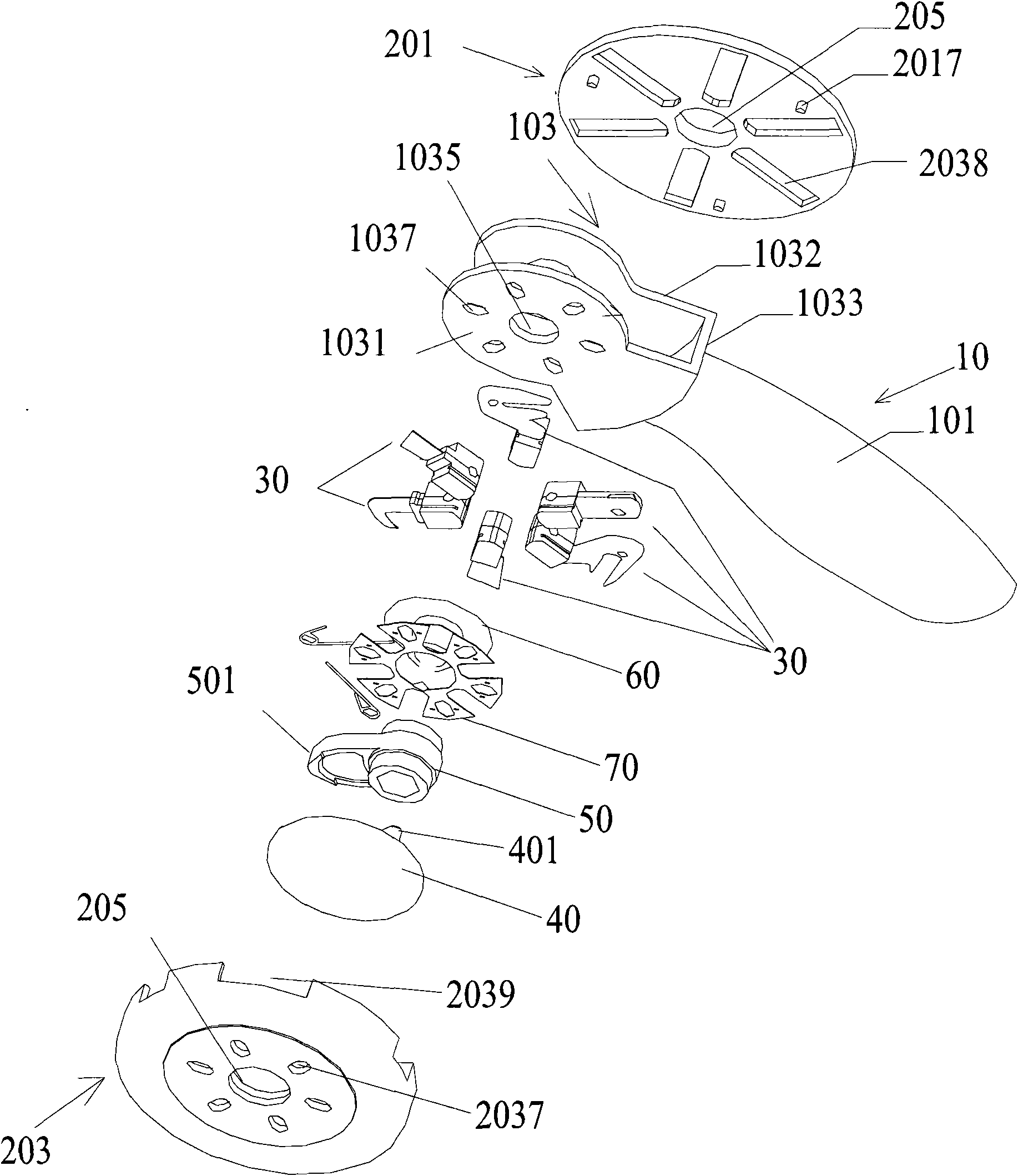
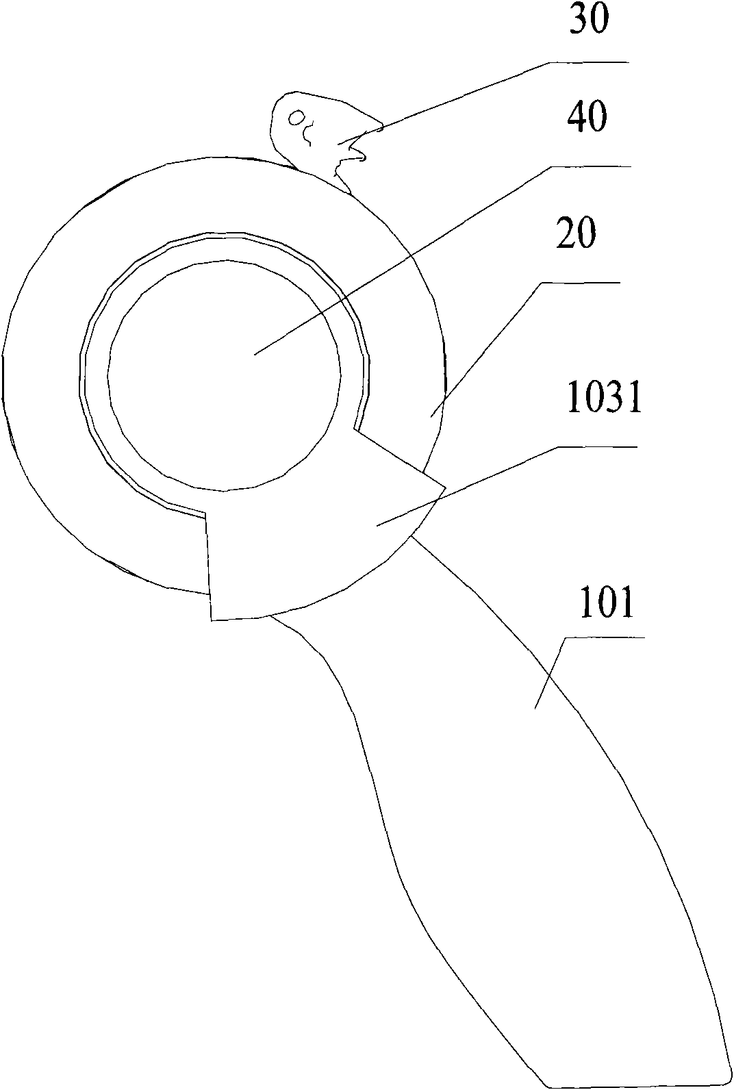
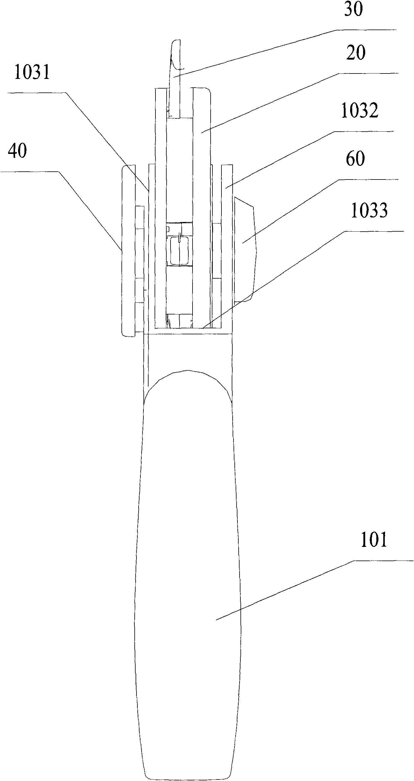
[0037] Figure 1 to Figure 9 The structure of the rotary knife according to the embodiment of the present invention is schematically shown. As shown in the figure, the rotary knife according to the embodiment of the present invention includes:

[0038] Handle 10, handle 10 comprises handle part 101 and support part 103 that are connected together, and handle part 101 has the shape that is suitable for people's hand to hold, and can be provided with the hanging hole (not separately shown in the figure) that is used for hanging on it, so that hang or Portable, the support part 103 includes a first side wall 1031, a second side wall 1032 and a bottom wall 1033 connecting the first side wall and the second side wall, the bottom wall 1033 is arranged on the handle part 101, the first side wall 1031 and the second The two side walls 1032...


PUM


Abstract

The invention provides a rotary cutter which comprises a handle, a rotating shaft, a rotating plate, at least one cutting tool and a shaft sleeve, wherein the handle comprises a holding part and a supporting part which are connected together, wherein the holding part takes a shape suitable for being held by hands; the supporting part comprises a first side wall, a second side wall and a bottom wall for connecting the first side wall with the second side wall; the rotating shaft is provided with a first positioning part; the rotating plate is rotatably arranged in the supporting part through the rotating shaft; the cutting tool is arranged in the rotating plate through an elastic part; an opening suitable for the cutting tool to extend or retract in the rotating plate is arranged on the edge of the rotating plate; the shaft sleeve is rotatably arranged in the rotating plate; the shaft sleeve is provided with a cam used for pushing the cutting tool out of the opening; the shaft sleeve is also provided with a second positioning part; and the first positioning part and the second positioning part are matched for driving the shaft sleeve to rotate by the rotating shaft. The rotary cutter can realize extension and retraction of a plurality of tool bits in rotation, can be provided with a plurality of cutting tools in an effective space, has a compact structure, saves space and cost, is convenient to carry and operate, and increases the working efficiency.

Description

technical field [0001] The invention relates to the field of knives, in particular to a rotary knife. Background technique [0002] In the field of packaging, people mostly use various knives to cut paper, cut packaging bags, cut packaging boxes and other operations. [0003] The inventor found that there are at least the following problems in the prior art: the existing knives can be folded and arranged in the handle of the knife, and can be rotated relative to the handle of the knife but cannot be stretched; A tool with a rotating handle and a retractable tool is not suitable for use in the packaging field and other related occasions. Contents of the invention [0004] The purpose of the present invention is to provide a rotary knife, which can solve the problems that the existing knife cannot be rotated relative to the knife handle and can be stretched, so as to be suitable for application in the field of packaging and other related occasions. [0005] The invention p...

Claims


Application Information

Patent Timeline
Patent Type & Authority Applications(China)
IPC IPC(8): B26B1/08B26B1/10B26B11/00
Inventor 钟敏
Owner 广东金辉刀剪股份有限公司
Why Eureka
Try Eureka