
Novel multi-layer printed circuit board

A multi-layer printing and circuit board technology, applied in the direction of printed circuit, printed circuit components, printed circuit structural connection, etc., can solve the problems of not being able to reach well, having a short service life, and not being able to reach the connection well, etc. To achieve the effect of protecting the circuit board

Inactive Publication Date: 2018-08-28
张秀芳
View PDF0 Cites 0 Cited by
  • Summary
  • Abstract
  • Description
  • Claims
  • Application Information

AI Technical Summary

Problems solved by technology

[0004] The purpose of the present invention is to solve the problem that only the fixed effect can be achieved on the basis of the electrical connection during use, and the stable connection cannot be achieved through the internal structure, and it cannot be achieved well in the Perform certain activities while stably connecting to facilitate maintenance, resulting in short service life. A new type of multi-layer printed circuit board is provided. In this device, expansion tubes, movable clips and fixed ring components can be used to improve the performance of multi-layer printed circuit boards. Fixity and stretchability have wide practicability to solve the problem that the existing multilayer printed circuit board proposed in the above background technology can only achieve a fixed effect on the basis of electrical connection during use. The structure can't achieve a stable connection, and it can't achieve certain activities while stabilizing the connection to facilitate maintenance, resulting in the problem of short service life

Method used


Image

  • Novel multi-layer printed circuit board
  • Novel multi-layer printed circuit board
  • Novel multi-layer printed circuit board

Examples


Embodiment Construction

[0025] The following will clearly and completely describe the technical solutions in the embodiments of the present invention with reference to the accompanying drawings in the embodiments of the present invention. Obviously, the described embodiments are only some, not all, embodiments of the present invention. Based on the embodiments of the present invention, all other embodiments obtained by persons of ordinary skill in the art without making creative efforts belong to the protection scope of the present invention.

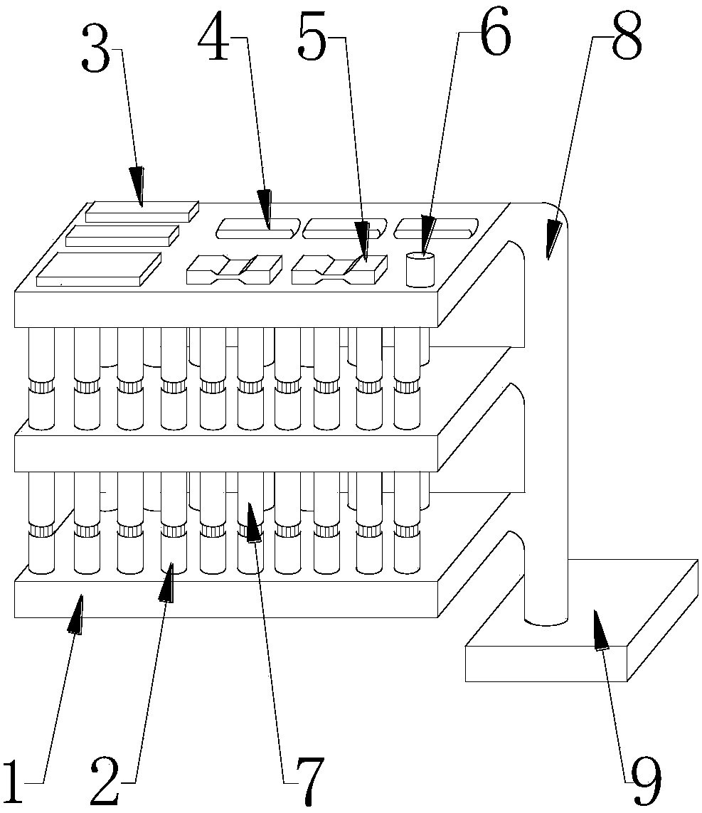
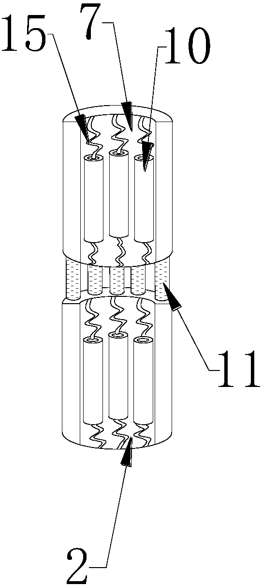
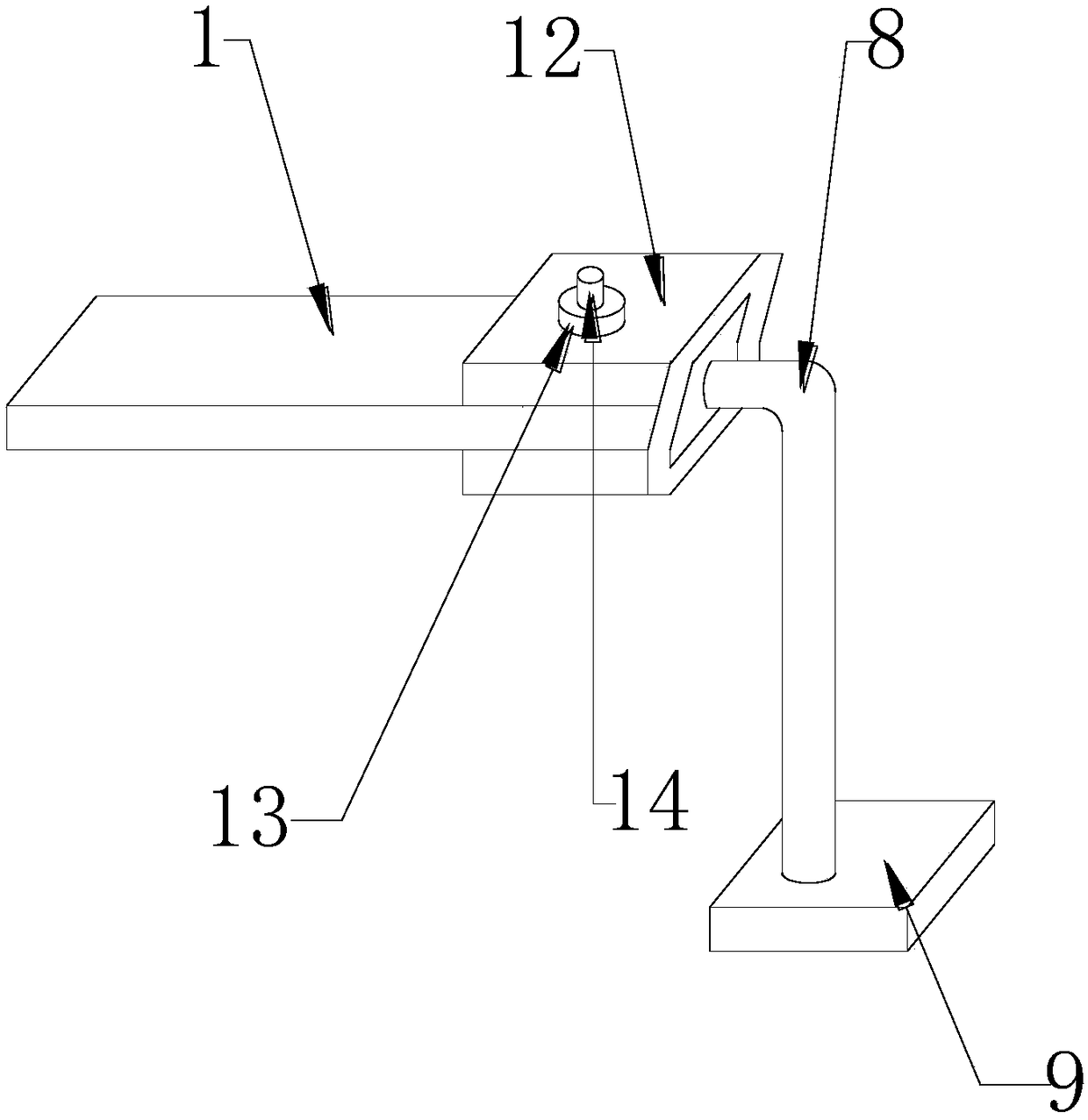
[0026] 1, circuit board used in the present invention, 2, lower fixed column, 3, patch triode, 4, triode, 5, chip capacitor, 6, electrolytic capacitor, 7, upper fixed column, 8, support column, 9, Base, 10, flexible pipe, 11, telescopic tube, 12, movable clip, 13, fixed ring, 14, movable nail, 15, electric wire can all be purchased through market or private custom-made gain.

[0027] see Figure 1~3 , in the embodiment of the present invention, the new multi-...


PUM


Abstract

The invention provides a novel multi-layer printed circuit board. The novel multi-layer printed circuit board comprises a circuit board, a paster triode, a triode, a paster capacitor and an electrolytic capacitor, wherein the paster triode is arranged at one side of the surface of the circuit board, and the paster triode is fixedly connected with the circuit board; the triode is arranged at the middle part of the surface of the circuit board, and the triode is fixedly connected with the circuit board; the paster capacitor is arranged on the surface of the circuit board, and the paster capacitor is fixedly connected with the circuit board; and the electrolytic capacitor is arranged on the surface of the circuit board, and the electrolytic capacitor is fixedly connected with the circuit board. The circuit board is fixed through an upper fixed column and a lower fixed column, and the upper fixed column and the lower fixed column are supported on the bottom surface of the circuit board andpenetrate through a positioning hole close to the edge of the board by a positioning pin, thereby achieving the effect of fixing the multi-layer printed circuit board, being suitable for production and use of the novel multi-layer printed circuit board, and having good development prospects.

Description

technical field [0001] The invention relates to the technical field of electronic equipment, in particular to a multilayer circuit board. Background technique [0002] Electronic equipment refers to equipment composed of integrated circuits, transistors, electronic tubes and other electronic components, which use electronic technology including software to play a role, including electronic computers and robots controlled by electronic computers, numerical control or program-controlled systems, etc. Electronic equipment generally refers to computers, printers, copiers, air conditioners, monitors, etc. Office equipment generally refers to office furniture, which may also include electronic equipment. [0003] The existing multi-layer printed circuit board can only achieve a fixed effect on the basis of electrical connection during use, and cannot achieve a stable connection through the internal structure, and cannot be well To achieve the effect of performing certain activiti...

Claims


Application Information

Patent Timeline
Patent Type & Authority Applications(China)
IPC IPC(8): H05K1/14
CPCH05K1/14H05K1/144
Inventor 张秀芳
Owner 张秀芳
Learn More