Method for continuously preparing phosgene
A phosgene and gaseous technology, applied in the direction of carbonyl chloride, etc., can solve the problems of poor heat tracing effect, affecting the working conditions of the separation process, and temperature drop
Inactive Publication Date: 2011-06-15
甘肃银光聚银化工有限公司 +1
View PDF11 Cites 30 Cited by
- Summary
- Abstract
- Description
- Claims
- Application Information
AI Technical Summary
Problems solved by technology
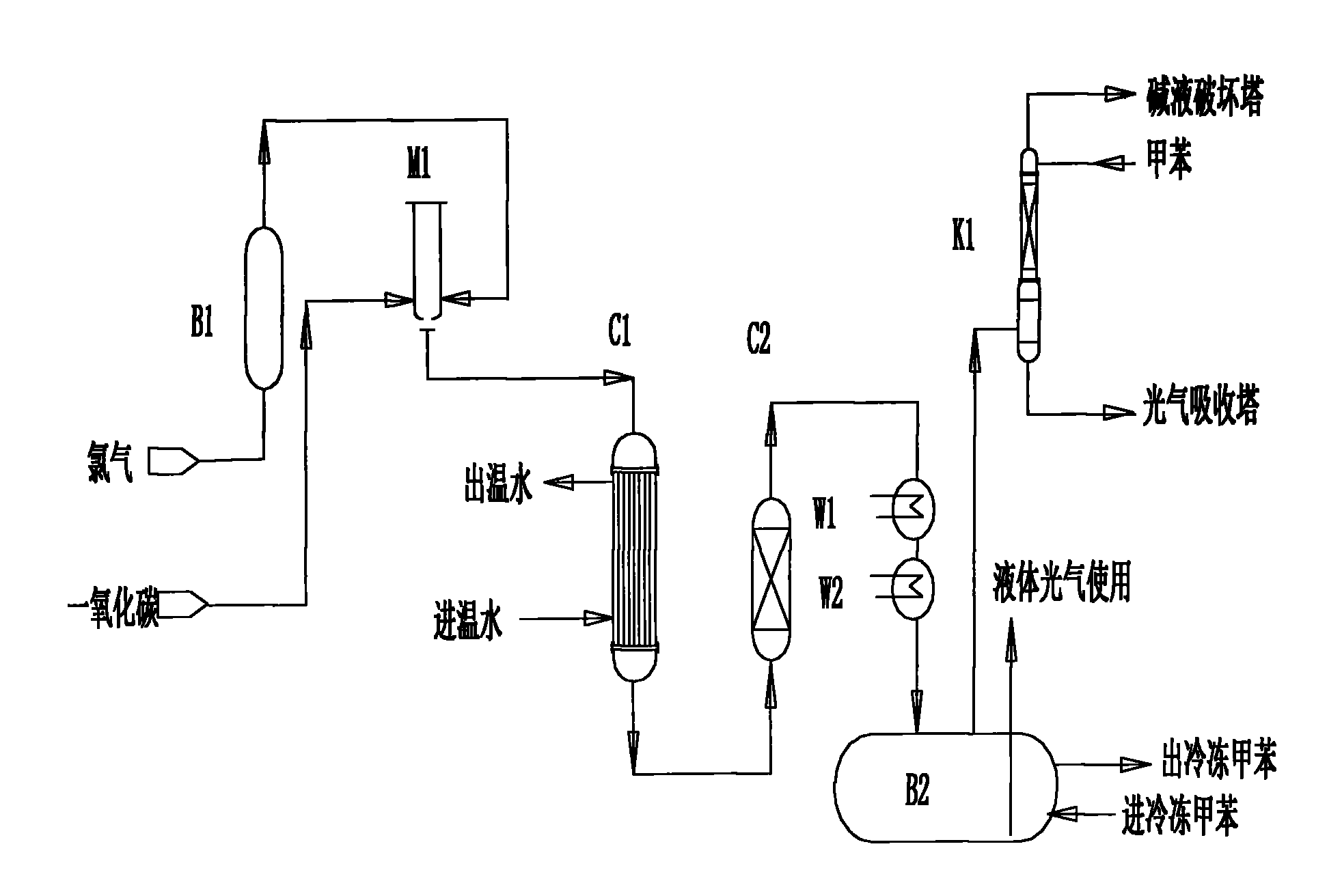
A new chlorine gas preheater B1 is added to solve the problem of chlorine gas liquefaction due to temperature drop and poor heating effect during the transportation process, resulting in excessive free chlorine content in phosgene, resulting in the formation of Cl-TDI in the photochemical reaction, which seriously affects the separation Problems with process conditions
Method used
View moreImage
Smart ImageViewing Examples
Examples
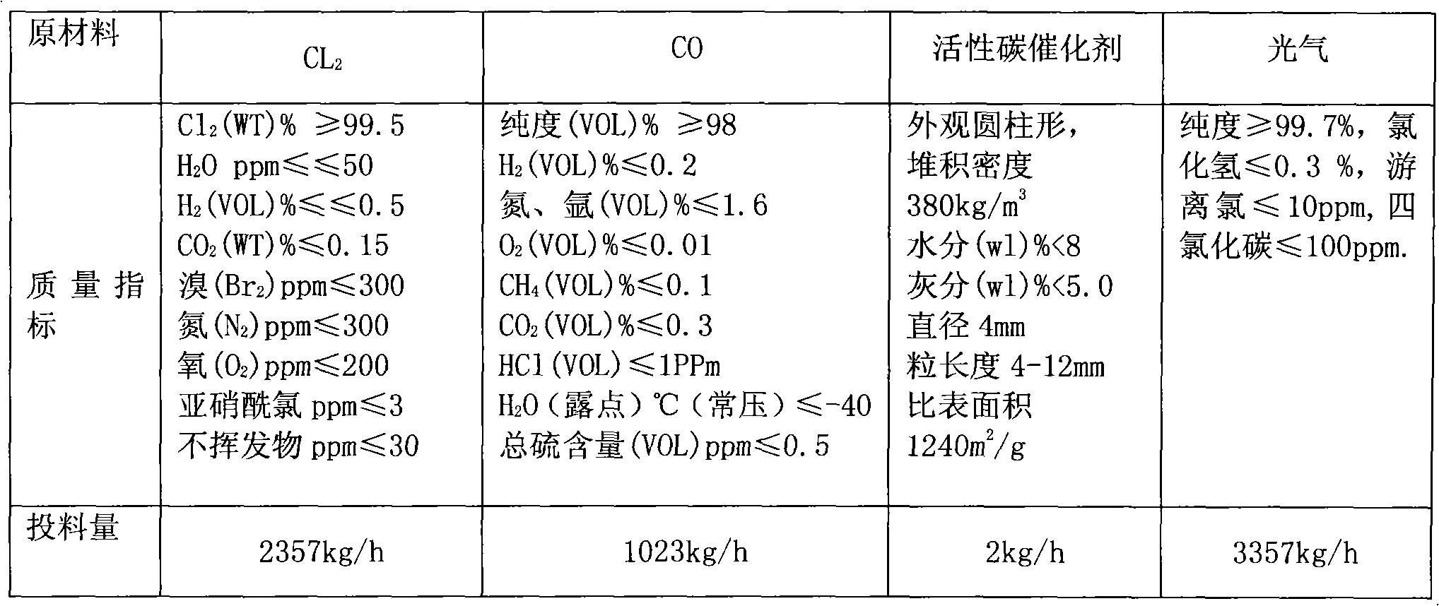
Embodiment 1
[0060] The process conditions of reactor and tower are controlled in the following table:
[0061]
[0062]
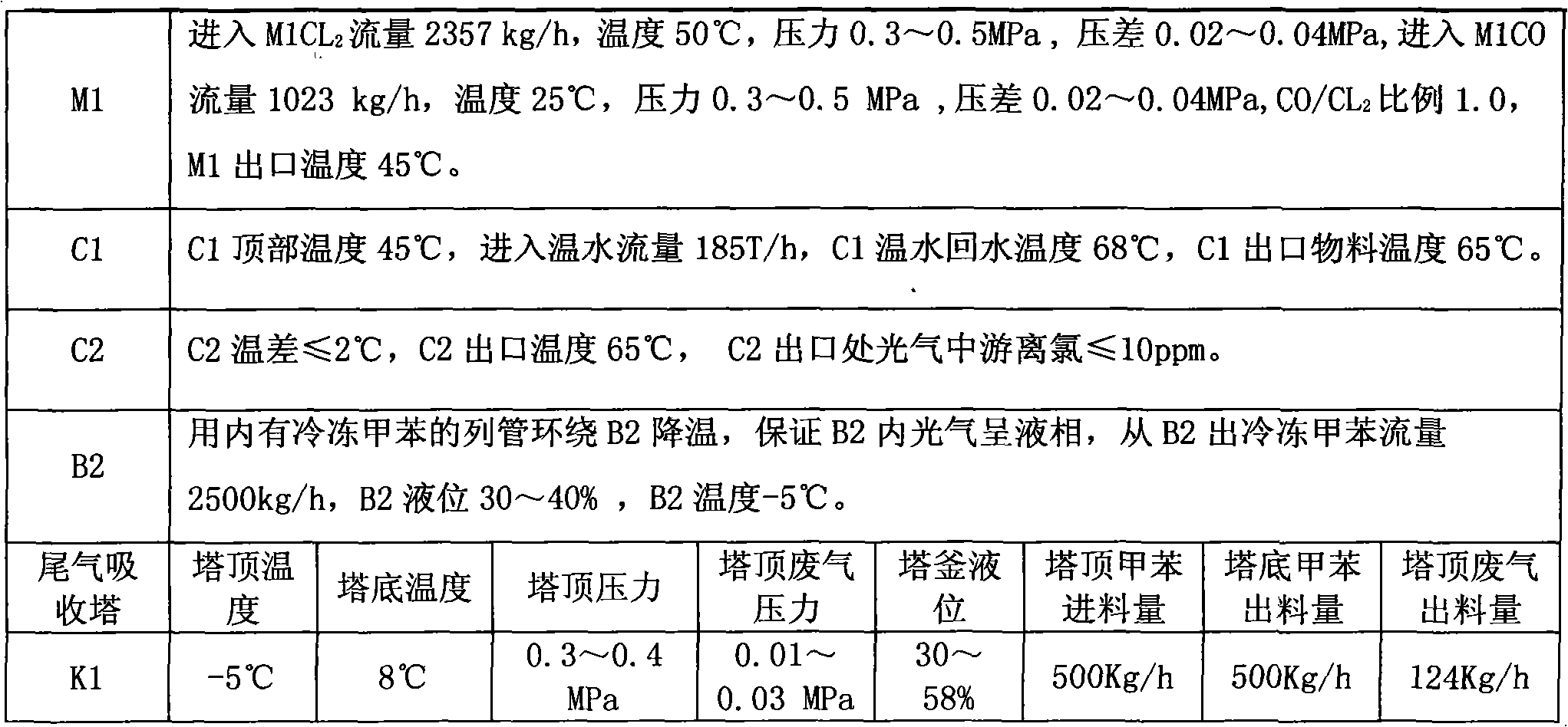
Embodiment 2
[0064] The process conditions of reactor and tower are controlled in the following table:
[0065]
Login to View More PUM
| Property | Measurement | Unit |
|---|---|---|
| diameter | aaaaa | aaaaa |
Abstract
The invention relates to a method for producing phosgene through the reaction of chlorine and carbon monoxide, and in particular to a method that chlorine and carbon monoxide are used to perform an exothermic reaction in a tube reactor in the presence of an activated carbon catalyst and generate phosgene. In the method provided by the invention, after chlorine is mixed with excess carbon monoxidein a mixer M1, then the mixture enters a tubular reactor C1 to react under the action of the activated carbon catalyst and generate phosgene and then passes through a protection reactor C2 to ensure that chlorine reacts completely; and the heat generated by the reaction is led out by a 60 DEG C cooling water system in closed cycle, the generated gaseous phosgene is cooled through W1 condensation and W2 condensation and enters a phosgene gas-liquid separation tank B2, the un-condensed gas enters an exhaust gas absorber K1, and -5 DEG C toluene is used to absorb and recycle phosgene in tail gas.
Description
technical field [0001] The invention relates to a method for producing phosgene by reaction of chlorine gas and carbon monoxide, in particular to a method for producing phosgene by exothermic reaction of chlorine gas and carbon monoxide in a shell and tube reactor in the presence of an active carbon catalyst. Among them, chlorine gas and excess carbon monoxide are mixed in the mixer M1, enter the tubular reactor C1, and react to generate phosgene under the action of an activated carbon catalyst, and then protect the reactor C2 to ensure that the chlorine gas reacts completely; the heat generated by the reaction is provided by a closed circuit The circulating 60°C cooling water system is exported, and the gaseous phosgene generated is condensed and cooled in two stages of W1 and W2, and then enters the phosgene gas-liquid separation tank B2, and the uncondensed gas enters the tail gas absorption tower K1. Absorb the phosgene contained in the exhaust gas and recycle it. Backgr...
Claims
Login to View More Application Information
Patent Timeline
 Patent Type & Authority Applications(China)
IPC IPC(8): C01B31/28C01B32/80
Inventor 强光明王立新张伟罗代晏耿天奇
Owner 甘肃银光聚银化工有限公司
Features
- R&D
- Intellectual Property
- Life Sciences
- Materials
- Tech Scout
- Unparalleled Data Quality
- Higher Quality Content
- 60% Fewer Hallucinations
Learn More Browse by: Latest US Patents, China's latest patents, Technical Efficacy Thesaurus, Application Domain, Technology Topic, Popular Technical Reports.
© 2025 PatSnap. All rights reserved.Legal|Privacy policy|Modern Slavery Act Transparency Statement|Sitemap|About US| Contact US: help@patsnap.com


