
Novel helical gear-worm gear speed reducer

A worm gear, helical gear technology, applied in the direction of gear transmission, belt/chain/gear, mechanical equipment, etc., can solve the problems of large vibration and noise, large transmission ratio grading interval, increased temperature rise, etc., and achieves various installation forms. The effect of optimization, wide speed ratio range and low noise

Inactive Publication Date: 2011-06-15
SHANGHAI LONGXIE ELECTRONICS TECH
View PDF0 Cites 3 Cited by
  • Summary
  • Abstract
  • Description
  • Claims
  • Application Information

AI Technical Summary

Problems solved by technology

For example, if the known PM reducer wants to obtain a large speed ratio (i=229) with the same power, because of the limitation that the transmission shafts in the box are arranged in a plane, when the output torque is the same, it is necessary to increase the deceleration ratio, the reducer is not only large in size, but also unstable in operation, high in vibration and noise, high in temperature rise, short in service life, and large in intervals between transmission ratios. At the same time, due to restrictions in the form of installation, only The user's one foot installation method cannot meet the user's needs for various installation forms. At this time, only foreign gear reducers can be used, but the price is very expensive.

Method used


Image

  • Novel helical gear-worm gear speed reducer
  • Novel helical gear-worm gear speed reducer
  • Novel helical gear-worm gear speed reducer

Examples


Embodiment Construction

[0011] The structural features of the present invention will be further elaborated below in conjunction with the accompanying drawings.

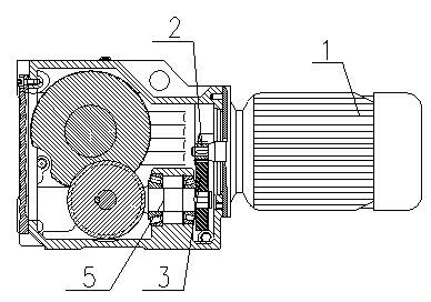
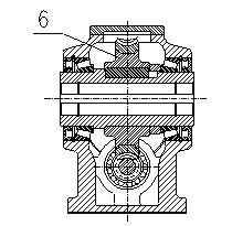
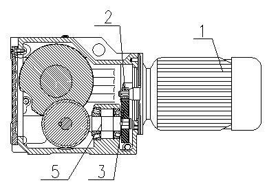
[0012] like figure 1 and figure 2 The new helical gear-worm gear reducer shown includes motor 1, first-stage pinion gear 2, first-stage large gear 3, box body, worm 4 and worm gear 5, flange, bearing, oil seal, retaining ring, oil seal ring, keys and fasteners, the motor 1 is installed on the input side of the box through the flange cover and fasteners, the output shaft of the motor 1 is fixed to the first-stage pinion 2 through the key, and the first-stage pinion 2 The first-stage large gear 3 is meshed; the first-stage large gear 3 is fixed on the pillow block of the second-stage gear shaft 4 through a key; the two ends of the second-stage gear shaft 4 are bearing blocks and are equipped with bearings, and the middle part is fixed with a worm 5 ; The worm 5 is engaged with the worm wheel 6 arranged above, and the worm wheel 6 is fixed o...


PUM


Abstract

The invention discloses a novel helical gear-worm gear speed reducer which comprises a motor, a primary pinion gear, a primary bull gear, a box body, a worm, a worm wheel, a flange disk, bearings, oil seals, retainer rings, oil seal rings, a key and a fastening piece, wherein the motor is arranged on the input side face of the box body through a flange cover and a fastening piece, the output shaft of the motor is fixedly connected with the primary pinion gear through the key, and the first pinion gear is meshed with the primary bull gear; the primary gear is fixedly arranged on a shaft bench of a secondary gear shaft; two ends of the secondary shaft are bearing benches and are provided with bearings, and the middle part of the secondary gear shaft is fixedly connected with the worm; the worm is meshed with the worm wheel which is arranged on the upper part of the worm, and the worm wheel is fixedly arranged on the output shaft through the key; and two ends of the output shaft are respectively provided with supporting bearings, the outer rings of the two bearings are respectively installed in the front bearing chamber and rear bearing chamber of the box body, and the outer sides of the two bearings are respectively provided with the retainer rings for holes, the oil seals and the oil seal rings. The speed reducer provided by the invention has all the functions of the worm gear speed reducer such as self-locking and the like, and the speed ratio range of the speed reducer provided by the invention is much wider.

Description

technical field [0001] The invention relates to a speed reducer, in particular to a novel helical gear-worm gear reducer, belonging to the field of speed reducers. Background technique [0002] At present, among all kinds of reducers known in the country, in the case of the same output torque, if the reduction ratio is to be increased, the volume of the box must be increased, that is, the entire volume of the reducer must be increased. For example, if the known PM reducer wants to obtain a large speed ratio (i=229) with the same power, because of the limitation that the transmission shafts in the box are arranged in a plane, when the output torque is the same, it is necessary to increase the deceleration ratio, the reducer is not only large in size, but also unstable in operation, high in vibration and noise, high in temperature rise, short in service life, and large in intervals between transmission ratios. At the same time, due to restrictions in the form of installation, ...

Claims


Application Information

Patent Timeline
IPC IPC(8): F16H1/20F16H1/24
Inventor 胡永宏
Owner SHANGHAI LONGXIE ELECTRONICS TECH
Learn More